diy solar

diy solar

MPP-SOLAR LV6548

I'd have to go to four to NOT rewire ... with three I'd need to rewire: two used for single phase 120V, the third for 240V appliances (I think - I haven't done the load calcs), which means I'd have to basically pull apart my main panel and separate the two systems. Trying not to spend an extra $3K (or $1.5K if I can even find another one right now), nor do all the rewiring work ...
You don't need 3, you only need 2 LV6548's to get 240V split phase.

Each LV6548 puts out 120V and you hook them up with the parallel cable, they will run opposite phases for the 240V.
 
is it that simple? makes sense intuitively but Is there a risk of the two mppts getting into a conflict?
kromc5 is doing it and I plan on Y'ing mine, run less wire. Why would it conflict? You're simply spreading the load between the 2 MPPT's.
 
Here's the latest ... I cc'd Jason at SanTan solar on my note to MPP Solar, and here was his response, as well as mine (nothing back from MPP Solar):

Hi Scott,

I received the following response from MPP last February when I asked.

“For LV 6548 . please note the PV max input current can be 2 panels in parallel. having the max input under 22A , it will all be fine.

I understand a 18A limit is too low and we have done a series test to confirm under 22A will be fine”.

Not sure if you can go over 22A. I suspect you will be fine. I am have not heard of any issues from previous customers.

Thanks

Jason

SanTan Solar

And here was my response to him:

Cool, thanks Jason. That number is all over the place (Ian at a US competitor of yours, according to the forum, said 23A) ... given how close I am to the edge of the range, I'd be quite hesitant to move forward if my panels weren't SW & SE, instead of due South and at 10 degrees off optimal during the summer.
You still have to stay under 4Kw per PV input..........
 
kromc5 is doing it and I plan on Y'ing mine, run less wire. Why would it conflict? You're simply spreading the load between the 2 MPPT's.
I don’t know, just seems too simple, but so long as all the panels are well matched there isn’t a reason it shouldn’t work
 
Not following what you mean here. You only need 2 LV6548 for split phase operation.

As for the 18A limit, you can do that per PV input. There are 2 PV inputs per LV6548. That's 36A per unit, times 2 units is 72A. Let's say you source 300W panels, VOC is 40V and ISC is 9.5A. You could go 5S2P and that is 3000W per string, times 4 strings, 12Kw for the total array.

The idea is to hit the sweet spot where VOC is up to 230V yet amps are around the 18A.

If you need more PV capacity, you can just add standalone SCC's, as many as you want. It won't make a difference to the LV6548's. The reason some will use 4 LV6548's is to reduce overall load on the units instead of running them near capacity 100% of the time.
The 6548's cannot split phase without being paralleled in even numbers ... need 2, 4, or 6 to do this ... adding another SCC to my two inverters would give me 4 5S2P for the MPP's with need for likely 2 more SCCs handling 6 panels each, and at least an extra $1000.

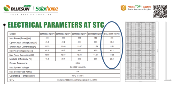
No room on my roof for 300W panels ... 455W at 11A mp already on the way. System will be 4S2P per Input at 164V mp and 22A mp, close to the clipping max. However, my panels are facing SE & SW ... 8% loss average = 10.12A Imp, which = ~20A mp per input, which is awful close to the 19.56A Imp that MPP used in the example ... I think I'm good ...
 
Ok, definitive answer from Andy Y. with MPP Solar Support Team:

"Please don't worry. PV input current 22A is ok and it will not cause the unit damage. We suggest that please keep the max PV input current within 25A. Thank you."

Without that 18A max PV input, this is quite a capable box for the price ...

Hey 25a, that's cool, a little wiggle room there :)
 
Hey 25a, that's cool, a little wiggle room there :)
Heh, a little ... that opens up almost all new panels out there to these boxes ... that's a big deal ... they really need to clarify this in their docs ... I'm quite relieved, as I purchased all my main equipment (PV, Inverters, Batteries) after doing only prelim analysis figuring that I'd work the details while everything was en route (exact wire sizes, exact panel placements, etc.) ... having to return these and practically start over would have been more than annoying ... so far, everything is working out ...
 
Hey 25a, that's cool, a little wiggle room there :)
25A makes sense, 4000W/25A = 160V input which is within the MPPT Voltage range spec of 90 ~230V.
4000W/18A = 222V, but since max PV input is 250V, you do not have much head room in cold weather, and when the panels get hot the Voltage drop below 222V so if that is the case then it will be hard to keep producing close to 4000W with that 18A max spec by trying to keep the Voltage up.
 
Last edited:
The 6548's cannot split phase without being paralleled in even numbers ... need 2, 4, or 6 to do this

Yes, that is correct. You stated you would have to use 3 and have to rewire the house..........

Then you stated you would use one for 240V which won't work, you need pairs to produce 240V split phase.

... adding another SCC to my two inverters would give me 4 5S2P for the MPP's with need for likely 2 more SCCs handling 6 panels each, and at least an extra $1000.

No room on my roof for 300W panels ... 455W at 11A mp already on the way. System will be 4S2P per Input at 164V mp and 22A mp, close to the clipping max. However, my panels are facing SE & SW ... 8% loss average = 10.12A Imp, which = ~20A mp per input, which is awful close to the 19.56A Imp that MPP used in the example ... I think I'm good ...
How many panels do you have? And what panels, I'd like to see the specs.
 
You have 4 PV inputs total. You can run 4S2P with four (positive and negative wires, which is 2 circuits) 10ga wires to your LV6548's. You can split each 10ga circuit with a Y at the inverter and input 11a into each PV input. You don't need to input 22a into one PV input.

Or you can run 4 PV circuits, each one to a PV input. I saw your possible array layout, biggest thing will be shading or how you group the array.

Make any sense?
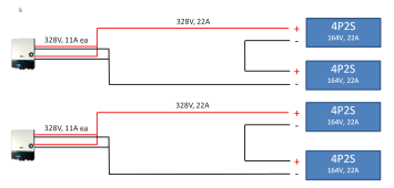
Is this what you're suggesting? Max PV input voltage on the 6548's per input is 250V ... don't think this would work unless I'm doing the math wrong ...
1642015981057.png

As for the shading ... yep, I'll be monitoring that closely ... will cut back trees as needed, add opitmizers as needed ...
 
You could do it that way. Each 4P2S is 46A (11.61 x 4) and 100V (50V x 2). Putting two 4P2S in series with another would be 200V, 92A which gets you up in wire size. You would be better served with 4S2P in each string to keep amps down, that does require 4 PV circuits as I stated. You could Y them (two 4S2P in parallel, total of 16 panels) , that would be 46A in between the Y on each end, probably take 6 ga or larger wire, dependent on length.

I was thinking incorrectly in the above post with the 11A, it would be 23A per PV input. I did have 4 PV circuits to the inverters, was thinking of 8 panels per PV input and forgot about the 2P.

Considering you have various angles and orientations of strings across the roof, you might be better served with 4S2P on the strings (50V x 4= 200V) and 23A per string) and feed each 4S2P to a PV input. Wire size of 10 or 8 ga depending on length. It all depends on what length you run and how you want to run it. In my case, PV goes underground to the house from a ground mount in buried conduit, each string is 13A so the Y makes more sense with 4 strings. Considering you have various lengths from each PV string, it might be just as easy and cheaper to run each string separate.
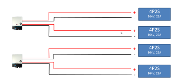
Cool, thanks. Yep, I'm pretty well settled on the 4S2P, one to each input. I created the schematic cuz I thought I might have been missing something ... I'll just modify it for the "Code Cops" I have to run all this past even though the plan is to go fully off-grid (no way will they not see me putting panels on my roof). Quite useful to have someone poking at my plans ... forces me to double / triple check my work ... appreciate it ...
 
Cool, thanks. Yep, I'm pretty well settled on the 4S2P, one to each input. I created the schematic cuz I thought I might have been missing something ... I'll just modify it for the "Code Cops" I have to run all this past even though the plan is to go fully off-grid (no way will they not see me putting panels on my roof). Quite useful to have someone poking at my plans ... forces me to double / triple check my work ... appreciate it ...
Can you show us the final diagram since the one in your post #394 will not work?
 
Can you show us the final diagram since the one in your post #394 will not work?
Sure! Here's the beginning, just the concept, modified from the above. Need to figure out grounding (if at all, the Inverter user guide said something about leakage, which I haven't researched yet), distances, wire sizes, fuses, breakers, switches, etc ...

1642025086883.png
 
Once you get it done I sure like to see what will happen to the PV input current when the PV Voltage drops below 164V, as shown right now based on calculation, it is 164V x 22A = 3608W, when panels get hot the Voltage will drop so I am looking forward to the end result.
 
Once you get it done I sure like to see what will happen to the PV input current when the PV Voltage drops below 164V, as shown right now based on calculation, it is 164V x 22A = 3608W, when panels get hot the Voltage will drop so I am looking forward to the end result.
Lessee ... alpha = .043% per degree Celsius from 25 ... hottest it gets around here is 110F = 43C ... 43-25 = 18. 18*.043% = 0.77% current gain. Not significant. What is significant it is the power output drop at that temp V = 95% * 164V * clipped 18A, to ~11kW, but my max power needs on worst day of summer was ~9.1kW ... so I'm covered ... that what you were looking for?
 
Last edited:
Back
Top