diy solar

diy solar

MPP-SOLAR LV6548

Ah, yes, I need to re-orient my thinking that way. So, essentially, the Battery Chargers is a load that will pull max 18A from PV? Then depending on my settings/priorities, the PV can/will power the house load as well, so long as there's enough power available?

MPPT sweeping, is how it does it, through varying the resistance on the PV circuit. When it fully releases the circuit, it let's the PV circuit go fully open, and voltage is high, amps is low (zero), to perform an MPPT sweep, it lowers the resistance on the circuit (for a brief sweep), which pulls the voltage down (gradually, as it scans), and the amperage on the PV circuit climbs, they do these MPPT sweeps every so often (on a schedule) in order to locate maximum power point in watts.

It can only load down the PV circuit until it reaches its max amp rating, and so the PV circuit will not 'pull' the voltage down beyond its max amps capability.

If no battery charging is needed and no demand on the inverter (so battery stays at full), then it will just fully release the PV circuit. If a demand is applied, or battery gets low, it will pull down the resistance on the PV circuit and get the battery charger going (regulating the charging amps via the PV load applied).
 
Last edited:
Wow. This is the second to last post on this 17 page thread (I've read the whole entire thing!!), and it's the answer I was looking for. I've ordered some 455W, 44Vmp, 11A Imp panels, and have no way to get them into my 2 inverters without running 4S2P per Input at 164V @ 22A max power. The damn manual even shows a 6S2P at 19.58A mp, over their 18A Max Input as stated on page 42 in their charging section. The many, many answers to this question are all over the place on this one thread, ranging from the inverter will shut down if over 19A to it'll just clip the amperage if over 18A to there's "flexibility" in that number (quite vague to be helpful). Any idea on the details on this? What exactly is this 18A number for? There are very few panels that are rated at less than 9A, so that 18A seems like a really stupid number, really debilitating for any system meant to power even an average home (me: 2400 sq ft, family of 4). If I can SAFELY go up to 23A, great (likely only around Noon in the summer will this matter at all for my planned system), what is that number actually for? I can't thank you enough for providing that number here ... I was mulling returning my two Inverters, and paying all the shipping, then restarting all the research to pick another one or two ...
The max wattage is a hard rule for GW and MPP Solar. You would be best served by heeding this warning. Add other SCC's instead of overpaneling. Start here and read what happens when you exceed the limits, and no, the system may not clip the input if a large load is placed on the inverters. https://diysolarforum.com/threads/v...l-specs-of-the-whole-system.11532/post-380819
 
The max wattage is a hard rule for GW and MPP Solar. You would be best served by heeding this warning. Add other SCC's instead of overpaneling. Start here and read what happens when you exceed the limits, and no, the system may not clip the input if a large load is placed on the inverters. https://diysolarforum.com/threads/v...l-specs-of-the-whole-system.11532/post-380819
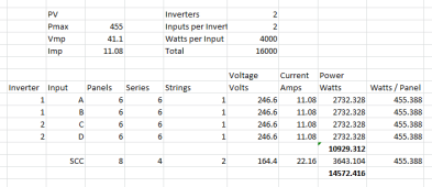
Heh, thanks for pointing me to that story. That whole experience seemed awfully complicated, and given all the various answers on here, this is likely a very complicated question. My planned system is NOT going over the Max Wattage, it will, on occasion, likely go over the Amperage rating on the Charger: 4S2P = 164V @ 22A mp = 3643 Watts < 4000 Watts per Input. From everything I've read, in theory the 6548 *should* clip at 18A (?). In some cases (shade, etc.), it may not as a strange situation "fools" the electronics (?). If I were to buy a separate charge controller, I'd end up with a configuration as attached, very close to the Vmax of 250V on the Inverter. Any thoughts on getting that close? Also, wouldn't a 19A DC breaker be a simpler option to use as a fail safe for the rare occasions (noon + summer + clear skies + fooled electronics) when something might go awry? @Samsonite801 @Lt.Dan any other thoughts here? Thanks everyone!! 1641747894461.png
 
Heh, thanks for pointing me to that story. That whole experience seemed awfully complicated, and given all the various answers on here, this is likely a very complicated question. My planned system is NOT going over the Max Wattage, it will, on occasion, likely go over the Amperage rating on the Charger: 4S2P = 164V @ 22A mp = 3643 Watts < 4000 Watts per Input. From everything I've read, in theory the 6548 *should* clip at 18A (?). In some cases (shade, etc.), it may not as a strange situation "fools" the electronics (?). If I were to buy a separate charge controller, I'd end up with a configuration as attached, very close to the Vmax of 250V on the Inverter. Any thoughts on getting that close? Also, wouldn't a 19A DC breaker be a simpler option to use as a fail safe for the rare occasions (noon + summer + clear skies + fooled electronics) when something might go awry? @Samsonite801 @Lt.Dan any other thoughts here? Thanks everyone!! View attachment 78984
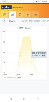
I just went back to July on my Solar Assistant and found this graph of my inverter clipping, to show what it does.

Screenshot_20220109-093215_Samsung Internet.jpg
 
I just went back to July on my Solar Assistant and found this graph of my inverter clipping, to show what it does.

View attachment 78991
Cool, thanks ... looks like it worked as designed. This also just makes sense, given that their own example in their User Manual went over the 18A Charger spec, and almost any new panels used today would be leaving a lot "on the table" as it were to configure with an extra SCC. If the max is 18A that it should EVER draw, then it would also make sense to put a 19A breaker in front, no? Well, looking at Amazon, a 20A breaker - don't see anything at 19A - which I assume is pretty standard anyway (I haven't gotten that far in detailing out my system)? Did the guy in that fire story maybe NOT have breakers to prevent this type of overload?
 
Heh, thanks for pointing me to that story. That whole experience seemed awfully complicated, and given all the various answers on here, this is likely a very complicated question. My planned system is NOT going over the Max Wattage, it will, on occasion, likely go over the Amperage rating on the Charger: 4S2P = 164V @ 22A mp = 3643 Watts < 4000 Watts per Input. From everything I've read, in theory the 6548 *should* clip at 18A (?). In some cases (shade, etc.), it may not as a strange situation "fools" the electronics (?). If I were to buy a separate charge controller, I'd end up with a configuration as attached, very close to the Vmax of 250V on the Inverter. Any thoughts on getting that close? Also, wouldn't a 19A DC breaker be a simpler option to use as a fail safe for the rare occasions (noon + summer + clear skies + fooled electronics) when something might go awry? @Samsonite801 @Lt.Dan any other thoughts here? Thanks everyone!! View attachment 78984

When determining how close you should go to max PV input on the inverter, in your case 250v, you need to use a suitable calculator (or do the math yourself) and factor in the coldest temperature the panels will see, as cold temps drive up Voc.

I don't remember the math off the top of my head, so I would just use a calculator like found on this page:


There are other guys here who know the math equation and could provide it here maybe.
Ah, thanks! I live in Austin, Texas ... plunked in -16 Celsius, lowest ever recorded answer came back 330V with 6S per input (and even at -1 which is more common: 319V) ... so it doesn't look like I have any other option but to run these at 4S2P, 164V (220V at -16 Celsius), 22A mp, and count on the clipping system to do its job, along with a breaker fail safe. @Lt.Dan, curious, what are your panel's Imp to your inputs?
 
Ah, thanks! I live in Austin, Texas ... plunked in -16 Celsius, lowest ever recorded answer came back 330V with 6S per input (and even at -1 which is more common: 319V) ... so it doesn't look like I have any other option but to run these at 4S2P, 164V (220V at -16 Celsius), 22A mp, and count on the clipping system to do its job, along with a breaker fail safe. @Lt.Dan, curious, what are your panel's Imp to your inputs?
Just ensure that breaker truly trips at 20a.

My max current was 24.8a. This was when I only had 1 inverter and had the panels in a 6s3p fashion. Once I got my 2nd inverter, I split them up to 6s2p and got more panels so I could stop wasting PV.
 
Heh, thanks for pointing me to that story. That whole experience seemed awfully complicated, and given all the various answers on here, this is likely a very complicated question. My planned system is NOT going over the Max Wattage, it will, on occasion, likely go over the Amperage rating on the Charger: 4S2P = 164V @ 22A mp = 3643 Watts < 4000 Watts per Input. From everything I've read, in theory the 6548 *should* clip at 18A (?). In some cases (shade, etc.), it may not as a strange situation "fools" the electronics (?). If I were to buy a separate charge controller, I'd end up with a configuration as attached, very close to the Vmax of 250V on the Inverter. Any thoughts on getting that close? Also, wouldn't a 19A DC breaker be a simpler option to use as a fail safe for the rare occasions (noon + summer + clear skies + fooled electronics) when something might go awry? @Samsonite801 @Lt.Dan any other thoughts here? Thanks everyone!! View attachment 78984
You don't show the VOC for the panels but from what I can gather it looks to be over 41.1V which is the VMP. I can tell you that putting 6 panels in series with a VMP of 41.1 is the 246.6V you have in your chart and this will damage the SCC in the units on cold days. MPP specs are Max VOC of 250V, recommended is a range of 90 to 230VOC.

Yes, I know some say you can run such a setup, they also sells units and kromc5 found out that what salespeople say is not always true.

You need to go off the VOC for your panels, not VMP.

You might be better off with a large array to have panels arranged to produce further thru the day. In other words, half the array pointed towards South-East and half South-West.
Ah, yes, good catch. I actually did plunk in the Voc, not the Vmp into the calculator for the Voltage numbers I showed above, so the 4S2P will keep everything within range, even on the fairly rare below freezing days here in Texas. Thanks much!!
 
Just ensure that breaker truly trips at 20a.

My max current was 24.8a. This was when I only had 1 inverter and had the panels in a 6s3p fashion. Once I got my 2nd inverter, I split them up to 6s2p and got more panels so I could stop wasting PV.

Cool, and it worked at almost 25A. Good to know. These breakers seem, er, important. :) Got a brand you'd recommend?
 
Spec'ing my battery system now, and happened to run across this from the manual on the PV input:

CAUTION: Before connecting to PV modules, please install separately DC circuit breakers between inverter and PV modules.

NOTE1: Please use 600VDC/30A circuit breaker

Step 1 : Check the input voltage of PV array This system is applied with two strings of PV array. Please
make sure that the maximum current load of each PV input connector is 18A
CAUTION: Exceeding the maximum input voltage can destroy the unit!! Check the system before wire connection.

I'm wondering if all this confusion is coming from the fact that, at START-UP, Step 1, before the system is initialized, you can blow it up at over 18A, then once it's connected and up and running, it can handle up to 30A, per their rating on the circuit breaker.

MPP Solar got back to me from my original question ... just a vague, "it can handle a bit more than 18A," a useless answer clearly from a very junior technical support rep. I sent clarifying questions back, and I also cc'd Jason at Santan Solar, where I bought them. I'll keep everyone posted ...

Ask them how much a bit is...
 
That would make about as much sense as the rest of their manual. So confusing ... and I'm a frickin' engineer ...

Yeah or did he mean literal binary? Like 18 ascii in binary is 10010, so 10011 would be 19 amps. I guess that could be what he meant by a bit more hehe...


Anyways, I'm curious what he replies back with. Thanks for inquiring on it. I'm just concerned at why MPP may not put built-in logic in the MPPT hardware or firmware to prevent it from pulling more current than it could even handle (to where it could fry itself).

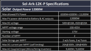
For example, on Sol-Ark 12k specs sheet, they explicitly say: 'Self-Limiting' I guess price plays a role too...

1641856698834.png

MPPT algorithm dictates that the sweep and control circuit, has precise control of the amps, by altering the charger load (by decreasing resistance on the PV circuit), could pull the voltage down (only as far as it needs to), drawing amps up to some predefined maximum, and stop it from going beyond that point which it can no longer safely handle.

I would like MPP to clarify how their MPPT controller logic functions.

I'm not worried about it myself on my LV6548's because I'm not approaching any of the limits. But it is useful to know how this inverter behaves when it comes to helping others out. If they don't have protections in place to safeguard from over-paneling, then we ought to know about it.
 
Last edited:
Sol-Ark 12k specs sheet post #359.
Max allowed PV Power: 6500W/6500W
MPPT range: 150 ~425V
So the Max DC Voltage spec is:
500V@18A (9000W), 450V@20A (9000W)
Max DC Current (per MPPT) is self limiting:
400V@18A (7200W), 300V@20A (6000W)

So if you have lets say 200V from panel instead of 300V, to get 6000W then the current will have to be 30A, if that is the case then you will never going to get 6000W if your PV is not at 300V, so it seems that you need to get the PV Voltage to be higher than 300V so you will not exceed the 20A limit.
Am I correct? I wonder why it has MPPT range down to 150V.
 
Last edited:
Back
Top