ianganderton
Auckland, NZ
We are still mainly using solar charge controllers primarily designed for lead acid and same for most other devicesNo, what I've was lifepo4 builds!
I wonder when it will start to change?


We are still mainly using solar charge controllers primarily designed for lead acid and same for most other devicesNo, what I've was lifepo4 builds!
To assist consideration, here is a table of the various fuse types and their Ampere Interrupt Capacity at various voltages.Class T fuse or even MRBF for that matter. Only thing I see is about sizing fuse/breaker and if they do mention fuse it is ANL or MEGA.
Type | MSRP USD | AIC per USD | AIC @ 14V DC | AIC @ 32V DC | AIC @ 48V DC | AIC @ 125V DC |
3 | 333 | 1,000 A | ||||
MAXI | 7 | 142 | 1,000 A | |||
8 | 250 | 5,000 A | 2,000 A | |||
12 | 166 | 2,000 A | ||||
MRBF | 19 | 263 | 10,000 A | 5,000 A | 2,000 A | |
ANL | 30 | 200 | 6,000 A | |||
45 | 444 | 20,000 A |
To calculate AIC rating/need, divide the max cell voltage by the internal resistance in ohms to get amperes.OK, that leads me to my next question. How do you calculate your AIC rating/need?


Nice explanation, really helps.To calculate AIC rating/need, divide the max cell voltage by the internal resistance in ohms to get amperes.
@Hedges mentioned 20,000 Amperes to be able to interrupt, but how to get to this number? 0.17 milliOhms was mentioned, and 3.65 Volts is the max LiFePO4 cell voltage. dividing 3.65 V by 0.00017 Ohm equals ~21,470 Amperes or about 20,000 Amperes.
if a given LiFePO4 cell had internal resistance of 1 milliOhm then the AIC needed would be 3.65 V / 0.001 Ohm equals 3650 Ampere or about 4000A.
this was my reference for how to know to divide voltage by ohms to get amperes
View attachment 113439Ohm's law - Wikipedia
en.wikipedia.org
hope this helps!
one tip, not all internal resistance meters can accurately measure internal resistance in Ohms on large capacity cells like 300Ah cells and alternate methods can be used to get more accurate data for those kind of cells.
Since I only have one 280ah 24v battery, I would think in my case adding MRBF and Class-T fuse would not make sense. I do think that a 250a Class-T fuse would be a good idea. Maybe not absolutely necessary but certainly won't hurt.personally my current primary fuse plan for 12v and 24v LiFePO4 batteries is one MRBF mounted on each battery positive, in addition to one Class-T fuse upstream of all paralleled batteries, and sure to physically protect the inbetween wiring.
")
What's interesting about this subject is that you see very little about in builds on internet, youtube, etc. I bet you'd have a hard time finding a build/diagram that shows the use of Class T fuse or even MRBF for that matter. Only thing I see is about sizing fuse/breaker and if they do mention fuse it is ANL or MEGA. I wonder why
@Will Prowse - how about a video testing lithium max current and fuses, maybe some of the shittier breakers too
What happens if a Lifepo4 battery is shorted out? What is the max current? Is it 20,000 amps?
Do the various fuse types protect against a direct short. What does it look like if they don’t?
It would be important learning for folks, educational, interesting to see and has the potential to be quite entertaining ?
Could be a whole series, similar to the “will it blend” old skool you tube
 www.researchgate.net

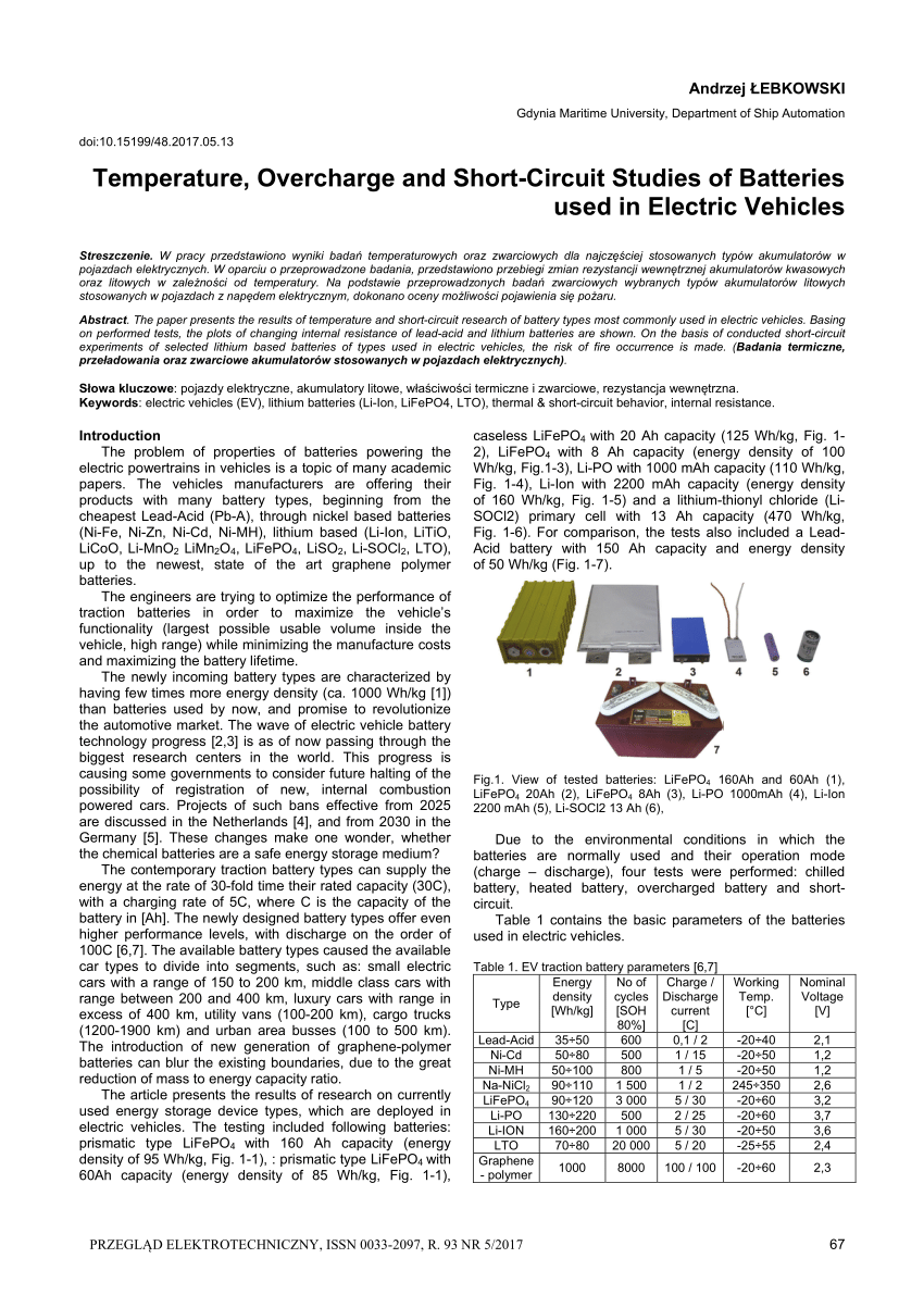
This publication has a graph of a shorted 160Ah 3.2V LiFePO4 cell:
(PDF) Temperature, Overcharge and Short-Circuit Studies of Batteries used in Electric Vehicles
PDF | The paper presents the results of temperature and short-circuit research of battery types most commonly used in electric vehicles. Basing on... | Find, read and cite all the research you need on ResearchGate
Higher voltage and higher Ah increases this, but you have a low of almost 1100A now with a single 3.2V cell.
This would be interesting-especially testing a couple of the more popular ones sold on Amazon!@Will Prowse - how about a video testing lithium max current and fuses, maybe some of the shittier breakers too
What happens if a Lifepo4 battery is shorted out? What is the max current? Is it 20,000 amps?
Do the various fuse types protect against a direct short. What does it look like if they don’t?
It would be important learning for folks, educational, interesting to see and has the potential to be quite entertaining ?
Could be a whole series, similar to the “will it blend” old skool you tube
This publication has a graph of a shorted 160Ah 3.2V LiFePO4 cell:
(PDF) Temperature, Overcharge and Short-Circuit Studies of Batteries used in Electric Vehicles
PDF | The paper presents the results of temperature and short-circuit research of battery types most commonly used in electric vehicles. Basing on... | Find, read and cite all the research you need on ResearchGate
Higher voltage and higher Ah increases this, but you have a low of almost 1100A now with a single 3.2V cell.
I think I saw that before, and it seems way low to me. Can only draw 6C with zero volt dead short?
Common automotive starter battery would blow that away. They source 700 to 800A at 8.5V (?) for a 12V battery.
I've seen reported 4000A from 100 Ah AGM.
This 160 Ah LiFePO4 single cell short-circuit current result doesn't pass the smell test. Maybe too much resistance in series?
I mean, it is possible the chemistry does this, but if so I doubt my 12V LiFePO4 jumpstarter the size of a lady's clutch could start a car.
Do you use the same amp fuse for both MRBF and Class T fuse when you do this? I was thinking I could add a higher amp Class T fuse for short circuits along with an MRBF fuse? It would just be a way to save money on blown Class T fuses. Or have I missed somethingpersonally my current primary fuse plan for 12v and 24v LiFePO4 batteries is one MRBF mounted on each battery positive, in addition to one Class-T fuse upstream of all paralleled batteries, and sure to physically protect the inbetween wiring.
I'm late on this thread, but you should add the AMH fuse at 1400 AIC per USD.To assist consideration, here is a table of the various fuse types and their Ampere Interrupt Capacity at various voltages.
The data is sourced from Blue Sea Systems, specifically the 250A type, or the highest possible rated alternative. Links in the name type.
"AIC per USD" is calculated using MSRP and the 32V DC AIC Rating or the Next Highest Voltage AIC Rating. For Class-T, the 125V DC AIC Rating was used. Its units are Amperes Interruptable Per USD.
The AIC per USD is for comparing AIC value of different fuse types. According to the respective MSRP listed, the Class-T fuse is more AIC amps per dollar than all the other fuse types offered on that site. This is using MSRP listed on Blue Sea Systems, which might not reflect real prices available. All MSRP prices rounded up to the next one.
Hope this helps somewhat. I also needed to see this table ?

 diysolarforum.com
Will try to get to that today, thanks for mentioning it.I'm late on this thread, but you should add the AMH fuse at 1400 AIC per USD.
The new king in the place when related to $/Breaking Capacity.
Eaton AMX and AMH Fuses alternative to Class T
I think I found a really interesting 10-15$ fuse alternative to Class T fuses. Eaton Bussmann AMH specs: -current ratings 350A, 400A or 500A -ultra-high interrupting ratings, up to 20,000 A. -voltage ratings, up to 125 Vdc Eaton Bussmann AMX specs: -current ratings 80A to 350A -ultra-high...
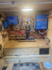
Not so fast there ..partner…every fuse I have is a classT ( 6 of 8 are shown here)… Or a class T tied in with a Buss mrcb so I have a cut off switch…. jus sayin.What's interesting about this subject is that you see very little about in builds on internet, youtube, etc. I bet you'd have a hard time finding a build/diagram that shows the use of Class T fuse or even MRBF for that matter. Only thing I see is about sizing fuse/breaker and if they do mention fuse it is ANL or MEGA. I wonder why
Haaa thats Ronnie…he’s my mascot for the power trailer…good dude..In the photo, just below the MPPT, is that a cockroach?
You are leaving the BMS out of the resistance total. My Overkill BMS has 3x 8awg 12" wires in and 3x 8awg 12" wires out, that's close to 24" of 3awg (0.427 milliohms). The PCB and solder also has resistance, and so will the FETs even when shorted. In fact the BMS has a 3 stage shutdown. One is slow software based for it's max current rating. The 2 hardware limits are much faster and have higher current limits to prevent false tripping from noise. If it failed to shut down you need the fuse, the BMS FETs are shorted.To calculate AIC rating/need, divide the max cell voltage by the internal resistance in ohms to get amperes.
@Hedges mentioned 20,000 Amperes to be able to interrupt, but how to get to this number? 0.17 milliOhms was mentioned, and 3.65 Volts is the max LiFePO4 cell voltage. dividing 3.65 V by 0.00017 Ohm equals ~21,470 Amperes or about 20,000 Amperes.
if a given LiFePO4 cell had internal resistance of 1 milliOhm then the AIC needed would be 3.65 V / 0.001 Ohm equals 3650 Ampere or about 4000A.
this was my reference for how to know to divide voltage by ohms to get amperes
View attachment 113439Ohm's law - Wikipedia
hope this helps!
one tip, not all internal resistance meters can accurately measure internal resistance in Ohms on large capacity cells like 300Ah cells and alternate methods can be used to get more accurate data for those kind of cells.