diy solar

diy solar

My DC breaker board - OK or redisgn ?

meetyg

Solar Addict
Joined
Jun 4, 2021
Messages
1,101
Hi there.
I'm working on my setup for 2 x 24v Lifepo4 (100Ah each) in parallel for a 24v 3k AIO Inverter.

I am planning to place this breaker board in a metal enclosure that I already have, so space is somewhat limited.

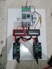
Basically what I have is two 125A DC breakers (one for each battery) going into busbars, and then busbars going into a larger main DC breaker (160A).

Since the batteries will be placed side by side below this board, this is the setup I've come up with:
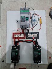
20230414_110818.jpg20230414_112101.jpg

As you may notice I also have a small DC breaker with inline resistor for manually pre-charging the inverter capacitors, before turning on the main DC breaker.

I'm not really happy with the criss-cross setup of the wires from the smaller breakers to the busbars. What do you think? Are there any implications? Will this cause any trouble?

Wire guage from each small breaker is 4 AWG Silicone insulated, and to main breaker is 2AWG.

Might be a bit on the small side, but I don't plan on pushing it anyways with the inverter.

I'd love to hear your thoughts.

P.S. ignore the red heat shrink on the black wires. I ran out of black, and will be replacing it when new supply arrives.
 
Normally you want the positive cables to be the same length and then the negative cables to be the same length. Your distances are short, so maybe it won't matter. Also, if you were to add the cable lengths of the positive and negative cables from the left breaker and compare that to the right breaker, the overall lengths would be the same. So it probably balances out.

I would have put the cable to the main breaker on stud 2 and the cables from the battery breakers on studs 1 and 3. This gives both batteries more balanced access to the main breaker.

Given the cable lengths involved, the imbalance that might be there is so small that it's almost a rounding error.

Where is your shunt going?
Yeah, alot of little unideal connections, but as you mentioned, I think overall lengths and resistances equal out.

I'm not planning to use a shunt. My batteries will each have its own JK BMS that I plan to connect to Solar Assistant for monitoring via RS485 to USB adapters.
 
Normally you want the positive cables to be the same length and then the negative cables to be the same length.
This just made me wonder.. is this really required? I know I see it sighted to keep the positive cables equal but I'm not following why it would be issue if the positive and negative total lengths are equal between the two different circuits? The total resistance would be equal between the two even when they have different length positive cables.
 
This just made me wonder.. is this really required? I know I see it sighted to keep the positive cables equal but I'm not following why it would be issue if the positive and negative total lengths are equal between the two different circuits? The total resistance would be equal between the two even when they have different length positive cables.

It's probably a wash. Do it either way.
 
Just wondering what your intention is with the two 125A breakers?

3kW @ 24V = 125A
So, you should be able to pull full load from the inverter with one battery disconnected - but do you want to?

With your board out of sight (in a box) and the system apparently working perfectly, you could have the situation where one battery is offline and the other is taking full load.
My purpose is for more capacity and redundancy.
So when everything is working fine, I will enjoy the double capacity. But if one battery (or BMS) fails, or if I need to take out a battery for maintenance (re-balancing?), my system will still be able to work at full load, but with less capacity.
Each battery has its own 200A BMS.
Another advantage is that when both batteries are in use, it will reduce the stress on the cells and BMS.
 
Great!
Just making sure you were aware of ways it might not behave as you want.
I'm thinking you want some sort of indicator to flag that one of the breakers has tripped.
 
batteries will each have its own JK BMS that I plan to connect to Solar Assistant for monitoring via RS485 to USB adapters
I guess that I'll see in SA that one battery is offline, if a breaker trips.
 
For the unbalanced wires, you could get data on the BMS once it’s up and running. May even be able to double check it with a clamp ammeter.

Even with perfectly cut to length matching wires, the loads between the batteries will not be even. I can’t remember the exact numbers, but on the lower end of a couple hundred watts, the lod is shared between batteries at around 7%, and when I pull 2 kw on my 3 kw inverter, the load is shared to within 3%.
 
Back
Top