diy solar

diy solar

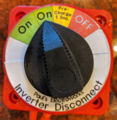
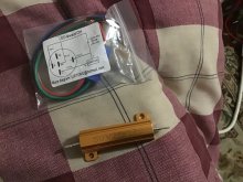
My Push Button Pre-Charger Install for the SW 4024 Inverter

I have not found this to be a problem. I have played with this some and what happens is that the inverter powers up but immediately goes into a low voltage disconnect mode.
See, that sounds to me like you are definitely giving it too much current. It it powers up enough that it does a low voltage disconnect, that is too much. You are only trying to charge up the capacitor(s) on the front-end, and that shouldn't take much current. So, I think a larger resistor would be better.
I think that is what is happening to my Schneider SW 4024. It tries to power on and then starts "clicking" like it is just not getting enough. And now that you say that, it might be that it is trying to go into low voltage disconnect. I need to test this to be sure.

But what you (Mr. @Horsefly ) are saying is that if it is even trying to power up enough to go into low voltage disconnect, that is too much and the Resister needs to be of even a higher OHM (like more than the 50 I am using)?? Like I need to be using an even higher OHM and not a lower one? Say like a 60 or even a 100 + OHM?
 
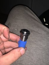
I mostly posted this for the parts list. I like the push button I found. It is really well made. So far so good.
i notice the switch is spec‘d for 12v but you put it in a 24v system. given that the switch is heavy duty rated for 60a, this may not be a problem? Has anyone else mentioned it? Is this something you are concerned about?
 
See, that sounds to me like you are definitely giving it too much current. It it powers up enough that it does a low voltage disconnect, that is too much. You are only trying to charge up the capacitor(s) on the front-end, and that shouldn't take much current. So, I think a larger resistor would be better.
Several things:
1) The normal procedure is to charge when the inverter is turned off. However, since humans are involved, it is advisable to design for mistakes. Consequently, this discussion is around what happens on pilot error, not in the normal sequence.
2) If the inverter is left on and the voltage is not enough to turn on the logic of the inverter, the capacitors are not getting charged very much either. Note: The resistance would have to be very high for the voltage to never get to the inverter turn on level.
3) The worst scenario would be that the voltage gets high enough to turn on the inverter logic and the drain from the inverter logic is enough to reduce the voltage and turn off the logic....and it sits there and oscillates between on and off. This almost-but-not-quite-on oscillation is not a state you want *any* electronics in. Furthermore, there may be no outward appearance that this is happening.
4) There may be a current value through the resistor where the turned on inverter is draining just enough current that an equilibrium is found that does not have any on-off oscillation and does not turn on..... but I do not know how to find that magic point and the voltage is going to be low enough that the capacitors are not very well charged.


I would rather have it power up and go into the low voltage disconnect state than to let it oscillate. At least then it is in a state the inverter was designed to handle. I am not saying anyone else is wrong.... just giving my perspective on things. The great thing about this forum is that we get to hear everyone's point of view and then pick what works for ourselves....

Note: I use the multi-position battery select switch as shown in link in my previous post. This setup ensures the pre-charge is engaged before the full on position is reached. With the low value resistor, even if the user rushes through the 'charge' position on the switch, the capacitors will be mostly charged. (This is why I prefer it over the push-button solution where the user could forget to push the button or waits too long between pushing the button and flipping the switch.)
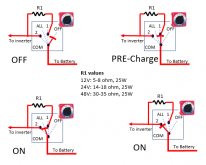
1618439361019.png
EDIT: Updated the image to add different values for R1. The resistor values are not critical,
Switch Position "Off" - "All Off"
Switch Position "1" - Pre-charge
Switch Position "ALL" - Full on
Switch Position "2" - Full on

Since the Perko switch does not allow going from off directly to 'All' or '2', there is no way to go to 'On' without going through Pre-charge.

My only complaint with this design is that the perko switch is rather bulky/big.
 
Last edited:
Well, I think we are going to have to agree to disagree. I don't think some of what you are saying makes any sense.
The normal procedure is to charge when the inverter is turned off. However, since humans are involved, it is advisable to design for mistakes. Consequently, this discussion is around what happens on pilot error, not in the normal sequence
Ok, we definitely have a problem here. If your inverter only has an ON state and an OFF state, you are going to have a spark in the switch whether you use the resistor or not. The current it draws in the ON state is too much for the capacitors to retain a charge for even a second. So then when you throw your main switch, the same arc will happen as if you didn't have the resistor circuit.
If the inverter is left on and the voltage is not enough to turn on the logic of the inverter, the capacitors are not getting charged very much either. Note: The resistance would have to be very high for the voltage to never get to the inverter turn on level.
Where are you getting this information? It doesn't actually take much to charge a capacitor, even a big one. The issue is that an uncharged capacitor appears essentially as a dead short for a fraction of a second. An LFP battery will happily pump lots and lots of current for that fraction of a second. You can plug in your own numbers here and see: a 50Ω resistor, a 24V battery and a 1000µF capacitor will fully charge the capacitor in about 0.2 seconds. The max current will be 24/50 = 0.48, and it will drop to less than half of that in 0.05 seconds.
I use the multi-position battery select switch as shown in link in my previous post. This setup ensures the pre-charge is engaged before the full on position is reached. With the low value resistor, even if the user rushes through the 'charge' position on the switch, the capacitors will be mostly charged.
This is probably fine, because - like I said above - a 50Ω will fully charge even a large capacitor in less than a quarter second, unless the inverter is on, in which case I have no idea what good the resistor does.
 
My rec uses a 66 ohm setup. 11 sec delay. It has now welded 2 contactors. About 10 cycles and Bam. Welded.
Very disappointed.

What voltage is your system?

The downside with the REC delay is the resistor is sized for the highest voltage it supports, 48V systems. So on a 12V system it's a bit slow. I just paralleled the REC resistors.
 
Ok, we definitely have a problem here. If your inverter only has an ON state and an OFF state, you are going to have a spark in the switch whether you use the resistor or not.
I am referring to the on off switch of the inverter. The on/off switch on *all* inverters that I know of does not disconnect the DC filter capacitors from the DC input. Therefore, without pre-charging you will get a spark regardless of whether the inverter is on or off. However, if the inverter is turned off, then even the control logic will not try to turn on and start sucking current as you charge the DC Filter Capacitors. With the resistor in the circuit what happens is the voltage does not get high enough for the inverter logic to turn on the inverter circuit. I know this because I have seen it work on several different inverters.
The current it draws in the ON state is too much for the capacitors to retain a charge for even a second.
That is not my experience. If the inverter is on and in the low voltage disconnect state it takes a second or so to turn off (The leds/display Turn off) when the DC is disconnected. The reason for this is the honkin big capacitors that we are talking about. Obviously this will vary from inverter to inverter. Again. I know this because I have seen it on several different inverters.

Also, if you look at the circuit that I use, the full on position is achieved while the resistor is still hooked up. (This is one of the reason I prefer the Perko switch solution over the push-button solution.

Where are you getting this information? It doesn't actually take much to charge a capacitor, even a big one. The issue is that an uncharged capacitor appears essentially as a dead short for a fraction of a second. An LFP battery will happily pump lots and lots of current for that fraction of a second. You can plug in your own numbers here and see: a 50Ω resistor, a 24V battery and a 1000µF capacitor will fully charge the capacitor in about 0.2 seconds. The max current will be 24/50 = 0.48, and it will drop to less than half of that in 0.05 seconds.
RC circuits were taught in one of my first electrical engineering classes in college. You are correct, it does not take much to charge capacitors. However, the charge on a DC capacitor is a function of the voltage on that capacitor. The higher the voltage, the larger the charge on the capacitor. So.... if the resistor is so large the DC voltage stays below the turn-on voltage of the inverter logic, the charge on the input capacitors are not as high as it would be at the turn-on voltage. That means when the switch turns fully on there will be a surge as the capacitors charge to full voltage.

BTW: Most inverters have several thousand uF of capacitance on the input.

Well, I think we are going to have to agree to disagree. I don't think some of what you are saying makes any sense.
OK. I am sorry it does not make sense to you. I have been wrong about things before and will be wrong about things in the future. However, I have built several systems using this and have iterated the design based on what I know about 1) electrical engineering and 2) the actual behavior of the inverters I have worked with. I am aware of several other people that have implemented the design and as far as I know it has been flawless for them as well. The design for my circuit has been downloaded by ~700 forum members. I can only assume at least a few of them have implemented it and I have heard no complaints. If you or anyone else has implemented it and found a problem, I would love to hear about it so I can either update the design or put warnings about the potential problem in the download.

 
What voltage is your system?

The downside with the REC delay is the resistor is sized for the highest voltage it supports, 48V systems. So on a 12V system it's a bit slow. I just paralleled the REC resistors.
48 v
 
i notice the switch is spec‘d for 12v but you put it in a 24v system. given that the switch is heavy duty rated for 60a, this may not be a problem? Has anyone else mentioned it? Is this something you are concerned about?
In the fine print of the Amazon ad there is a spec for 24v as well and I asked the seller what the rating would be. It's half the rating of 12v
 
...Also, if you look at the circuit that I use, the full on position is achieved while the resistor is still hooked up. (This is one of the reason I prefer the Perko switch solution over the push-button solution...
first, let me say thanks for everything you’ve done on the forums here. You’ve contributed a lot of knowledge in both conversation and downloadable material for people.

Second, I like your precharge design. It seems elegant.

I will be using a momentary switch for my precharge circuit. I, also, will be able to turn the battery on while the resistor is still in circuit, so i don’t particularly see how the Perko is any better than momentary, in that regard. I think your design provides for a little more ”it just works” or perhaps one could refer to it as idiot-proofing. I kind of like the aesthetics of my choice better, though. I feel like I am still getting both function and form. Depending how I wire the switch, the LED will either be always on or on when pressed. I will wire so on when pressed. Pardon my dirty fingers. Did spark plugs and wires today.

here’s an Amazon link for the switch.


5B0A5846-8EBB-4B56-B69B-DD96D2D32303.jpeg
A2DC71BD-56D1-40BF-944A-CA153FC3F73B.jpeg7524C71B-F74B-4F22-AFF0-C63FA0FA952D.jpeg
 
Last edited:
I plan to use a common toggle switch with positions OFF-ON-ON
First on is resistor, second on will switch the BMS to allow discharge.
 
I plan to use a common toggle switch with positions OFF-ON-ON
First on is resistor, second on will switch the BMS to allow discharge.
If the BMS doesn’t allow discharge, then how will precharge work? Are you bypassing the BMS with your precharge circuit? That’s not a decision I would make, but it will work.
 
I think your design provides for a little more ”it just works” or perhaps one could refer to it as idiot-proofing. I kind of like the aesthetics of my choice better, though.
Yup. Since I build systems for other people that are not as knowledgeable about all this stuff, I try to make it as idiot-proof as I can. (but nothing is truly idiot proof.

I also agree that the big red Perko switch is not very aesthetically pleasing.... I even said essentially the same a couple posts back. However, since other people will be using the system, I put priority on making it difficult for them to screw it up.
I still have a big red (blue sea) dual circuit battery disconnect, but I’ve got a cool led precharge light too... ?? I’m laughing at the ridiculousness.
 
RC circuits were taught in one of my first electrical engineering classes in college. You are correct, it does not take much to charge capacitors. However, the charge on a DC capacitor is a function of the voltage on that capacitor. The higher the voltage, the larger the charge on the capacitor. So.... if the resistor is so large the DC voltage stays below the turn-on voltage of the inverter logic, the charge on the input capacitors are not as high as it would be at the turn-on voltage. That means when the switch turns fully on there will be a surge as the capacitors charge to full voltage.
Well, my EE education was probably different than your EE education, but that isn't a good reason for this disagreement. I think we are just talking past each other. :unsure: You said "the charge on a DC capacitor is a function of the voltage on that capacitor" but actually this isn't really true. If you looked at the page I linked or read my logic: A capacitor is essentially a short to a DC source until it is charged. The charge on the capacitor is a function of the current going through it, until it reaches the voltage across it. That's it. It will take as much current as it can, until it can't.

The resistor limits that current. That's all. The whole purpose in doing this silly thing is to limit the current inrush to the inverter. When first touched, the inverter has ZERO resistance. So the only thing that is limiting it is the resistor. That's my point.

So you said inverters may have multiple thousands of microfarads in capacitors. Fine. We are still talking about much less than a second for 0.5A of current to charge, which is fine for 50Ω resistor.

I'm glad - and appreciative - of your contribution to the forum. I just hope it is well thought out. I am confident that whatever you are suggesting is of no help for an inverter that is in the full on position. I don't really understand why it would be good to suggest it to somehow address the current rush into an inverter that is left on. Too each his own.
 
Can I connect the battery positive to a 3 pin toggle switch with one toggle option being a line with a 50 watt 25 ohm resistor and the other toggle being the positive battery going straight to inverter positive
1800 Watts at 12 volts is 150 Amps. That looks like it would overwhelm that switch. I prefer the picture @MrM1 posted above using a circuit breaker to carry the high amperage after the precharging circuit has done its job.
 
Its gotta be connect. I manually switch it off with no load .
It's the kilovac ev200adana. It's a light weld that can be released by cycling it 10 times fast.
 
Back
Top