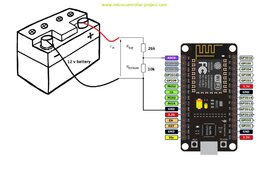
I built a setup to replace the battery monitors I have on my cars that reports voltages via wifi to a website since they discontinued the monitors so I needed a replacement.
Everything works perfect on 9v batteries aka the kind you put in a voltmeter etc.
I need to measure 12v car batteries and lifepo4 batteries and such. It wont work. I can't figure it out.
I have a 47k ohm resistor on the 12v+ wire and a 10k resistor on the negative side. I tap between these to get the voltage down to where the analog to digital connects.
When I power up the system without connecting the adc wire to the battery I want to test it the unit works fine. It connects to the wifi and reports 0 volts which is correct.
When I have the wires hooked to a 9v battery and power it up it works fine and connects to the wifi and reports 9 volts to the server.
When I connect it to the 12volt lifepo4 it won't connect to the wifi and of course doesn't send info to the server.
If I connect the wire with it running it never sends results to the server even though it sent a 0 volt report before hooking up the test leads to the battery.
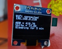
Ive ordered an lcd panel to attach to the thing so I can see more info on whats going on but I can't wrap my head around the battery size being the issue.
It's not a voltage issues since I added more resistors to bring the test voltage down to even lower than what the 9v battery reporting with the old amount of resistors.
Is there some crazy part of the ah capacity of the battery being able to overload the resistors? I can't imagine this being possible but I'm reaching for any possible explanation at this point. I could understand if I was drawing any real amps across the resistors but I'm just measuring voltage not running something would draw amps unless the Arduino thing can draw amps when first connected somewhere on the analog to digital circuit???


