diy solar

diy solar

Need Help Wiring Pack Please

heavy-impact

New Member
Joined
Apr 28, 2020
Messages
71
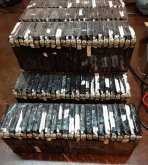
I need suggestions on wiring this 36v pack made up of 240 smaller 3.6v packs. I want to keep it as compact as possible within reason.
Each cell measures 3"x2.25"x3/8" and has it's own BMS with temp sensor.
The wire I have on hand is 18ga bare tinned copper, 18ga tinned silicon insulated, 6ga insulated tinned and 105amp flat braided tinned copper strap. I have Kapton tape and shrink wrap as well.
Max output is 96 amps but I'll never draw more than 70 amps.
I have them in bundles of 24 in the picture. I was thinking 24p10s but I'll go with whatever you think is best.
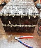
Pack1.jpgPack2.jpgReality.jpg

I'll fab an insulated aluminum box for the pack after it's wired and have a Anderson connector fastened to the top.


_____________________________________________________________________________________________________________________________________________________________

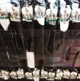
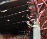
These cells do not come as advertised on batteryhookup https://batteryhookup.com/products/3-7v-4-4ah-16-28wh-w-bms-no-wires. They advertise them with two 2a BMSs mounted on top each pack with the solder pads easy to reach.
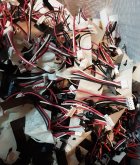
What you see in the pics on the right is what you really get with a single 4a side mount BMS wires randomly attached on them (even though you order no wires) and strong glue and fiber tape covering all solder pads. Batteryhookup ignored all emails about this and never changed their advertisement. I wasted days cleaning these up to make them usable. I'm not angry, just disappointment in being mislead. I'll still do business with them but I know to ask questions now. Everything else I've ordered from them has been as advertised.
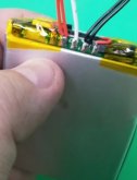
False advert.jpg 4.4 sent.jpgMisleading mess.jpg
 
Last edited:
I can solder 18ga wire to the bms solder pads with no problem. The trouble I have is how to get whatever buss bars around to the other packs or if this is even the best way to wire it. I'm one of those people that has to work it out in his head before doing the work.
When I listed the wire I have on hand to choose from I forgot 6ga solid bare copper, tinned.
 
The mechanical layout is where I would start. Are they used? Do you know if they are well matched. If not I think you would need to design the mechanical layout so that you can pull parallel groups of 12 or 24 out of the pack to replace them with another group that is better matched. I assume you have plenty of extras. If you are paralleling them in groups of 24 you only need a BMS connection at that buss bar unless there is some internal battery protection device for each cell. In parallel they will all measure the same so I do not know what the advantage would be of the cell level wires.
 
The mechanical layout is where I would start. Are they used? Do you know if they are well matched. If not I think you would need to design the mechanical layout so that you can pull parallel groups of 12 or 24 out of the pack to replace them with another group that is better matched. I assume you have plenty of extras. If you are paralleling them in groups of 24 you only need a BMS connection at that buss bar unless there is some internal battery protection device for each cell. In parallel they will all measure the same so I do not know what the advantage would be of the cell level wires.
Each 3.6v 4.4ah pack has a 4 amp bms with temp sensor. I'm looking for help with the wire routing and any other suggestions.
Thanks
 
Each 3.6v 4.4ah pack has a 4 amp bms with temp sensor. I'm looking for help with the wire routing and any other suggestions.
Thanks
I can't help with the wiring routing unless I know what the physical layout is. Sorry my mind works that way.
In terms of other suggestions that you asked for I have the following:
Temp sensor would be useful information on a cell basis. How are you going to monitor that? Is it a separate set of wires for temperature? Again. sorry if I am not giving you the answer you want but unless I know the outcome I can't help with the design. That is why I am ignoring the BMS wire because the data (voltage) will be the same for every cell in the parallel group. It would be redundant to measure that 20 times because physics says it will always be the same for cells in parallel. It would be a waste of time to run 40 BMS wires only to find out they all measure the same and I could have run to the the buss and saved a lot of time and energy. That is not the same for temperature and that data could tell you which cell is getting stressed.
 
Last edited:
I can't help with the wiring unless I know what the physical layout is. Sorry my mind works that way.

Temp sensor would be useful information on a cell basis. How are you going to monitor that? Is it a separate set of wires for temperature? Again. sorry if I am not giving you the answer you want but unless I know the outcome I can't help with the design. That is why I am ignoring the BMS wire because the data (voltage) will be the same for every cell in the parallel group. It would be redundant to measure that 20 times because physics says it will always be the same for cells in parallel. That is not the same for temperature and that data could tell you whch cell is getting stressed.
The layout is in the first picture but I'd rather have them three high with the last two packs being on top. This would make the pack measure 9"x9"x9". The temp sensor only feeds the bms.
 
Until you decide whether is is one row of 24 or three rows of 8 tell me more about the BMS so I can understand to better help you. What kind of device do the BMS wires connect to? does it have inputs for 480 wires (2 x 240)?
 
Until you decide whether is is one row of 24 or three rows of 8 tell me more about the BMS so I can understand to better help you. What kind of device do the BMS wires connect to? does it have inputs for 480 wires (2 x 240)?
There are pictures in the first post. A bms on each cell with just a + and -. They charge and discharge through the same connection.
10 cells make 36v. I have 240 so I figured 24 parallel and then put those in series.
 
Unless I know anything about the BMS and what it is connected to l would suggest you forget about the BMS wires and wire the pack together in rows of 24 with buss bars for positive and negative on top that could be connected to the next group of cells to make a 24P10S pack.
Then I would get a 10S BMS and wire it to the buss bars.

TOTALLY agree ... I would NOT mess with the BMS stuff until a) you know what it actually is ... and b). After you get all the batteries connected ... Personally I rarely trust a used BMS regardless where I get it ....
 
The BMSs are soldered to each cell and they work fine. They make this pack safer and that's one of the main reasons I chose these.
I feel like no one is looking at the pictures or link that describes the cells. I do appreciate you trying to help me though. hug[1].gif
 
The best picture I got was from your other post where you told us that the end result will be a 9" x 9" cube that weighs 50 lbs and will be powering a trolling motor. That confirms my suggestion to get a 10S BMS, wire it to the buss bars of the 24P cell groups and forget about those 480 little BMS wires. As @ghostwriter66 implied that many wires would drive me to drinking. Because of the virus I could not go Salmon fishing in Alaska so I am vicariously urging you to get this pack wired so I can take some comfort that I helped one person get on the water. :)

With a propulsion application you want a good coulomb counting BMS so you know how much is left in your pack to get back to the dock. Without that you may be limited to only fishing upwind unless you have a paddle. ;)
I have two other battery packs. The main one is a LG 165ah intended for chevy volt but never used. It will power the boat for days. The second is 200 LG MJ1 cells that I purchased new for 70ah. I also use these in my house to power a 3000w inverter when the power goes out. Both have active balancers that keep every cell within .003v of each other and neither has a bms. The following pics are from the balancer of big LG pack after more than two days on the water. It took the balancer about a week to get the balance that close after I first installed it but it hasn't changed more than .002 since. The second pic is from today at storage voltage. The balancer run time is at the top of each.
Balanced -.jpg
balanced2 -.jpg
 
I read the specs of these new batteries more carefully and discovered that the chemistry is Lipo also known as LiPoly. It charges and discharges to the same voltages as NMC but is much more volatile that NMC. You may want to do some more research to learn how to manage them. They are very popular in the RC hobby niche because of their energy density and light weight.

I think you are wise to try to find a way to connect up the temperature probes because that is the first sign that something in going wrong. No problem while on the water because you can just throw them overboard but be very careful charging them at home.
Each cell has it's own BMS... if there's a problem it turns the cell off.
 
Each cell has it's own BMS... if there's a problem it turns the cell off.
BMSs do not put out fires. I think what you mean is it disconnects the cell. They can still self combust. You are putting a lot of faith in a BMS that you know little about.There is a good reason RC hobbyists discharge them to 50% when they bring them home.
Good luck
 
Last edited:
BMSs do not put out fires. I think what you mean is it disconnects the cell. They can still self combust. You are putting a lot of faith in a BMS that you know little about.There is a good reason RC hobbyists discharge them to 50% when they bring them home.
Good luck
You've made eight posts in this thread with zero advise on topic so it makes you look like a troll. Especially when you have zero confidence in 240 BMSs that you know nothing about yet you have total confidence in any additional BMS I would be willing to purchase. You have ignored every fact presented in order to make your unfounded fire argument. Please go troll someone else and I will ignore any further nonsense from you.
When you're totally ignorant on a subject it's best to not comment.
Here's a dead short test on one of your deadly fireball liPo cells. Watch the massive fireball.

 
Back
Top