diy solar

diy solar

Needing help with victron wiring

JaseyB

New Member
Joined
Sep 22, 2021
Messages
75
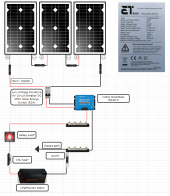
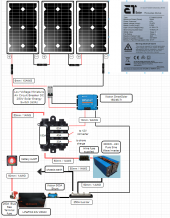
Guys have bought a Victron 150/45 MPPT here:


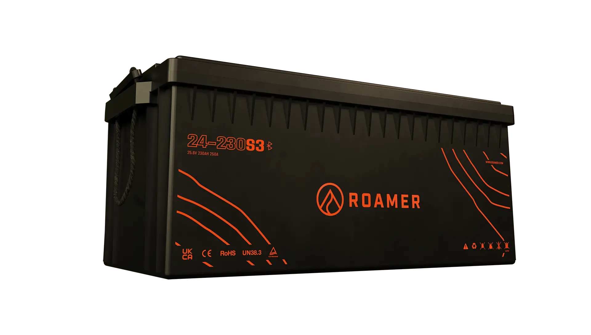
hooking up to a 24V 230Ah LiFePO4 battery:


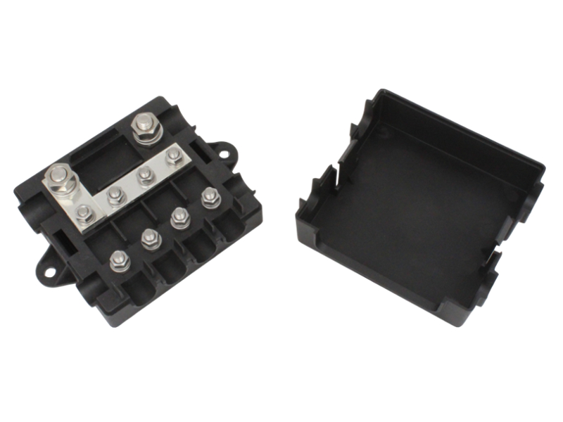
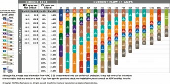
What I need to know is the amp output of this to get my busbar, fuses and wiring sized.

Specs are in German(?) so that doesn't help me understand much.
Any help would be greatly appreciated. Thanks.
 
Diagram to help your design, since details are not provided I had to guess, but should be similar to your needs.

Main fuse F1, MRBF Bluesea or better Tag HRC fuse with holder,

Other fuses Midi or Mega link fuses, F2,3,4,5 these should be mounted as near as possible to the positive buss bar.
Ideally a fuse distribution block could be used,
distribution fuse holder.jpg


All cables automotive or marine quality with hydraulically crimped terminations.
Roamer 24 volt system.jpg

Note all installation manuals for Victron and most other products can be found on the internet.

Mike
 
Last edited:
Diagram to help your design, since details are not provided I had to guess, but should be similar to your needs.

Where I am with my diagram so far (still learning/work in progress) :
 

Attachments

  • wiring diagram.PNG
    wiring diagram.PNG
    211.9 KB · Views: 20
Where I am with my diagram so far (still learning/work in progress) :
Remember, circuit breakers and fuses are meant to protect the cable. 63amp breaker for a 10ga cable is on the high side.

I for one would keep the 24v negative isolated and forgo the chassis ground you call out , others will argue different.
 
The breaker in the solar feed is only an isolator , the solar panel current cannot exceed the panel SC current. Overcurrent is not needed and will never 'trip' in a single string.
The negative of the service battery needs chassis / frame/ metal body bonding for safety. To suggest otherwise in a RV application is poor advice. However I acknowledge there are alternative views but it's a requirement, at least in the UK, to fully meet professional standards.

Mike
 
Diagram to help your design, since details are not provided I had to guess, but should be similar to your needs.

Main fuse F1, MRBF Bluesea or better Tag HRC fuse with holder,

Other fuses Midi or Mega link fuses, F2,3,4,5 these should be mounted as near as possible to the positive buss bar.
Ideally a fuse distribution block could be used,
View attachment 107109


All cables automotive or marine quality with hydraulically crimped terminations.
View attachment 107105

Note all installation manuals for Victron and most other products can be found on the internet.

Mike

Mike, SOOOoo many thanks for this. ?:giggle:

It probably is everywhere on the web if you know where to look and what to look for. I don't have much more than the basic understanding at the mo and am looking to learn.
This info however is invaluable so I thank you for this. It allows me to get some more things on order and more pieces of the puzzle for me. (y)
 
Diagram to help your design, since details are not provided I had to guess, but should be similar to your needs.

Main fuse F1, MRBF Bluesea or better Tag HRC fuse with holder,

Other fuses Midi or Mega link fuses, F2,3,4,5 these should be mounted as near as possible to the positive buss bar.
Ideally a fuse distribution block could be used,
View attachment 107109


All cables automotive or marine quality with hydraulically crimped terminations.
View attachment 107105

Note all installation manuals for Victron and most other products can be found on the internet.

Mike

wait ... is this right? 50mm wire? AWG 1? Seems HUGE!!!! :LOL:
 
wait ... is this right? 50mm wire? AWG 1? Seems HUGE!!!! :LOL:

Your Victron is a 45amp charger. You need to have cabling / fusing for 45 amps plus buffer (as required by your laws, whatever those are). AWG 1 certainly seems excessive. Now if we are talking about your 3000 watt inverter, or the cabling from the battery to the busbar, that's another story.
 
Your Victron is a 45amp charger. You need to have cabling / fusing for 45 amps plus buffer (as required by your laws, whatever those are). AWG 1 certainly seems excessive. Now if we are talking about your 3000 watt inverter, or the cabling from the battery to the busbar, that's another story.
Can you expand on this. I know NOTHING about this stuff 'cept how to wire a plug.
I was told 24V would make the sizes smaller?
 
The breaker in the solar feed is only an isolator , the solar panel current cannot exceed the panel SC current. Overcurrent is not needed and will never 'trip' in a single string.
So you are trusting a Chinese product not to backfeed. Happens.
The breaker in the solar feed is only an isolator , the solar panel current cannot exceed the panel SC current. Overcurrent is not needed and will never 'trip' in a single string.
Go ahead and ground if you want. When your brakes do not work. One of the many reasons why they are isolated. One of the main reason Orion made DC-DC convertors isolated.
 
50mm2 is the cable csa, the diameter with insulation is about 8mm This is the recommended size for a 3000 watt Inverter at 24 volts . See instructions for Victron 3000 watt inverter.
Also

The 45 amp charger I specified at 10mm2 (7awg).

With due respect JaseyB, it does seem you are operating outside your comfort zone with this project. Slow and steady with lots of you tube and reading to 'learn' skills. Providing you fit fuses and cable as recomended your van wont burn down.
The 230 AC side is slightly more demanding but provided you follow best practice and comply with the regulations it will work out OK. Professional testing of the competed system is recomended.

Mike

I have not been shy in stating this and this is exactly why I'm here in beginners corner. I am relying on teh power of the internet to learn from guys with experience. It is not an impossible task and there are plenty less "capable" than I that have done this. I just wanna do it right.

I just don't understand ppl telling me that using 24V would reduce my wiring considerably and yet now I'm being recommended 1 AWG wire. I'm not saying it's wrong, I'm not saying I'm against it. I'm saying I don't understand.
 
Can you expand on this. I know NOTHING about this stuff 'cept how to wire a plug.
I was told 24V would make the sizes smaller?
Look at a cable carrying watts. If a cable can only carry 10amps then at 12 volts it can carry 120watts (Watts = Amps x Volts). Now if you put 24 volts down that same cable rated for 10amps you know have 240watts (Watts = 10 X 24) Do it with 48volts and you have 480 watts.

If you turned that into real world what would take for a 12 volt system might need a 2 gauge cable, a 24 volt system a 4 gauge cable and a 48v system a 6 gauge cable, all to carry the same wattage.
 
Guys can you please appraise my latest wiring diagram (attached) for any errors?
Any and all help greatly appreciated.

Cheers
 

Attachments

  • wiring diagram.PNG
    wiring diagram.PNG
    259.4 KB · Views: 17
Seems OK.

Thanks :giggle: ?

I'm concerned about the wiring of the victron MPPT.

6mm / 10AWG going in and 10mm / 8AWG out? Does this seem correct? Considering the inverter needing 50mm/1AWG connecting wires?
Guess I'm still thinking of this like a water or pressure system. Not quite got that to click in my head just yet but hopefully it will soon.
The inverter is pulling 125+ amps for 3000 watts from the battery. The charge controller is 45 amps to the battery.

Maybe you would like this printable chart?
 

Attachments

  • DC_WireSelectionChart.jpg
    DC_WireSelectionChart.jpg
    213.8 KB · Views: 13
Last edited:
I have not been shy in stating this and this is exactly why I'm here in beginners corner. I am relying on teh power of the internet to learn from guys with experience. It is not an impossible task and there are plenty less "capable" than I that have done this. I just wanna do it right.

I just don't understand ppl telling me that using 24V would reduce my wiring considerably and yet now I'm being recommended 1 AWG wire. I'm not saying it's wrong, I'm not saying I'm against it. I'm saying I don't understand.
Because your getting diffent opinion's from different people…there all good answers just from different experiences and different takes on the same topic..I went through this at first…you will have too as well . It’s part of the learning curve….
There is usually no exact answer for what we seek At first ….After while you will narrow it down to a few choices ,of which you will have to make your own decision …There are very few absolutes in this hobby craft…As you grow you will find the path you like ….. it takes a while … I hope that helps with your question at the end of your statement about not understanding what you were being told…remember it’s not always an exact science.
Good luck…
Jim.
 
Bondi
The breaker in the solar feed is only an isolator , the solar panel current cannot exceed the panel SC current. Overcurrent is not needed and will never 'trip' in a single string.
The negative of the service battery needs chassis / frame/ metal body bonding for safety. To suggest otherwise in a RV application is poor advice. However I acknowledge there are alternative views but it's a requirement, at least in the UK, to fully meet professional standards.

Mike
Chassis bonding in capper vans and TVs in the uk to BS standard requires 230 vac to be chassis bonded , the same stipulation does not allow to low voltage DC however
 
Back
Top