Im a lefty and write horribly so I apologize for the chicken scratch
Rather than explaining how you want to do it, please explain what you are trying to achieve. Provide all of the information we need to help you answer your questions.
What you have asked:
1. How to install the inverter with a bypass to address inverter failure,
2. How to make the inverter supplement the grid to lower bills and to provide backup power with zero export.
What we know:
1. You have a 200A service,
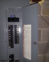
2. You have a Square D Homeline load center,
3. You don't want to mess with your load center, you just want to add a breaker to it to make it work,
4. You want the least expensive option.
Here are some questions:
1. Do you still need the inverter bypass?
2. Does your meter panel have a disconnect breaker in it?
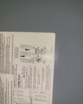
3. Can you provide the model number of your Homeline load center?
a. Do you know how many amps your load center is rated for?
b. Does your load center have a main breaker in it at the top?
c. If your load center has a main breaker in it, what size is it?
4. Do you know how many amps or watts you use on average and peak?
5. Do you know where and how you are going to install the inverter relative to your load center?
6. How are you going to connect the PV power source(s)?
a. Are you going to connect PV panels directly to the inverter?
b. Are you going to connect existing PV grid-tie inverters to the output of the inverter?
c. Are you going to connect existing PV grid-tie inverters to the input of the inverter?
Here are some answers:
1. You can only connect the grid to the inverter's AC input.
2. You can never connect the grid to the inverter's AC output.
3. You can never connect the inverter AC input and AC output to the same panel.
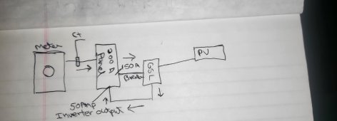
4. The purpose of a large pass-through is to allow you to put the inverter between your meter panel and your main load center. This means that you
do not need a breaker for the inverter. You simply connect the meter output to the inverter input and the inverter output to the existing load center. The meter is currently connected directly to the load center or to the load center's main breaker if it has one. You just reuse those wires.
5. Typically your meter has a breaker and your load center does not have a main breaker. The wires come from the meter and connect directly to the lugs in the load center. If your meter does not have a breaker, then you must have a main breaker in your load center. If this is the case, you MUST add a breaker to your meter panel if it allows one to be added, or you must add a new panel in front of the inverter with a main breaker in it so that you can disconnect your house from the grid. This is NOT optional if your meter panel does not currently have a breaker in it. If your service is 200A and you want to be able to use 200A, the breaker and panel must be rated for 200A. If you don't use 200A, then you can downsize everything to what you really use at and from that point.
Now with those answers you should be able to see how it all works. You connect your meter to your inverter, then your inverter to your load center. If you are connecting your PV panels directly to the inverter, the PV power will supplement the grid and reduce your power bill and you
can have zero export. If the grid goes down
with or without batteries, the inverter will continue to run and your PV power will continue to provide power to your house
and charge your batteries.
If you have existing grid-tied inverters on your house and connect them to the output of your inverter, then they will also supplement the grid and reduce your power bill and you
can have zero export. If the grid goes down
and you have batteries, the inverter will continue to run and your PV power will continue to provide power to your house. However, the PV power
will not charge your batteries as far as I understand the inverter. You will have to read up on that.
If you connect existing grid-tied PV inverters to the input of the inverter, then they will also supplement the grid and reduce your power bill. However you will
not have zero export, and if the grid fails, the grid-tied PV inverters will turn off and
they will not provide power to your house or to the inverter and will not charge your batteries.
None of what I have explained here addresses the inverter bypass in the event of inverter failure. The diagrams I provided previously describe that. If those are unsatisfactory, then there is another option, but it requires that your load center have a main breaker and you must be able to add an interlock kit to it at the top of the panel where the main breaker is. This solution eliminates one panel and its breakers but still requires a double-pole double-throw switch and one breaker and back-feed retaining brace. It will not support monitoring or charging the batteries or PV inputs when in grid-only mode, so that is why I did not provide that solution the first time. The solution I have already provided does. Given that you want 200A, you are going to have to pay a bunch for everything to be 200A capable, and I don't get the impression that you have the knowledge to pull it off without hurting or killing yourself.
If you have more questions, that is what the forum is for, but you need to provide all of the information necessary for us to provide a complete answer.