I'll see if I can write up something this weekend, the code is still sitting on my old laptop (and is embarrassingly bad!)@elusivesd : Can you share the custom code for emulating the SDM630? Really keen on making something like this work! Even just a github link would be awesome!
Background: Originally needed a solution to control backfeed on a GTIL2 inverter without the use of the original CT clamps. If unfamiliar, the GTIL2 functions in a closed loop - will "ramp up" power output when input is pulled low, and "ramp down" power output when pulled high (from memory, don't shoot me if reversed). Steady power output effectively looks like a 50% PWM duty cycle.
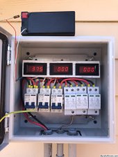
Hardware: CircuitSetup single/split phase energy meter => ESP32 (Arduino sketch) => GPIO pulsing pseudo-pwm to GTIL2 inverter input
GTIL2 software logic:
Loop:
- Read power from ADC
- If value > threshold (~100W), set GPIO output pin to RAMP_UP
- if value < threshold, set GPIO output pin to RAMP_DOWN (excess backfeed, reduce power)
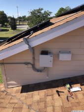
Eventually, I outgrew this setup and moved on to the LXP inverter. Of course, metering options are different - either by using CT clamps, or Eastron SDM meter over RS485.
Hardware modified: CircuitSetup => ESP32 => RS485 => LXP
LXP software logic:
Loop:
- Read power from ADC
- Set global vars (Total Watts, Volts A, Amps A, Volts B, Amps B, etc..)
- Convert values to register compatible format, set registers (emulating Eastron SDM)
- If/when LXP requests register data for information, latest info will be retrieved
Each loop will complete within about 15ms (~1 AC cycle), limited by the ADC and LXP polling rate. The data itself is near real-time.
There's more to it, but this is a high level overview of functionality. Let me know if you have any questions!