diy solar

diy solar

New Lux Power LXP-LB-US 12k / GSL-H-12KLV-US with 200A AC Passthrough Current (US Market)

Status
Not open for further replies.
Greetings,

Finally figured out what I want.....

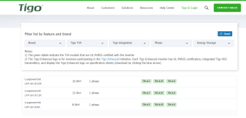
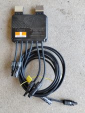
Will the TIGO TS4-A-O 700w 15A optomizers work with this 12k? If not; which ones will and are they better??
Planning on using solar assistant....or if there is anything better, let me know

Thanks
mine did works with tigo optimizer, but i was losing 30% production so i had to remove it.
 
The current status is that we have completed the compatibility test for Tigo's PVRSS (RSD functions) so far. Tigo has reached out to us regarding compatibility tests for their O series (optimizers), but it will take a longer time to complete these tests/certificates, likely another 2-3 months.

For information on the PVRSS tests/certificates with Tigo: https://www.tigoenergy.com/ul-pvrss?e0d3a03b page=4
1684088103457.png
 
The only reason I wanted to add them to each (30) would be to monitor the panels operation. I don’t have shaded areas. Is there another way without optimizers and Solar assistant or another software package?
 
Per panel monitoring requires per panel measurements. I think that is found only in optimizers.
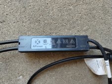
If you require RSD, you can use Tigo "F" series but no monitoring. Some brands of inverters have keep-alive for other brand (SunSpec compliant) RSD boxes, so select your package of equipment to work together.

Monitoring per-panel may not provide much value unless panels are bad. Inverter would show power on one MPPT. I got a clamp DC ammeter and compared multiple PV strings, found a string that was low. I had to unplug panels and test individually to find which was bad. Failed panels is a quality/durability issue, so brands with a good history would be preferred.

Another way to locate possibly bad panels is IR camera. More blotches that other panels would suggest a problem. History of system power production would be a reason to go looking.

My RSD cost $40 each, so 30 of them would be $1200. You can get a nice IR camera and clamp ammeter for considerably less. Mine have two PV inputs, but that would still be $600. Plus transmitter.
 
Last edited:
The only reason I wanted to add them to each (30) would be to monitor the panels operation. I don’t have shaded areas. Is there another way without optimizers and Solar assistant or another software package?
Great, your panels don't have shaded areas, then I think it's good enough that the current software can show each string's data log? Each panel's data, as @Hedges said, is only available for optimizers, not able to just be solved by some software. good discussion, there's a lot to do for these improves.
 
If junction boxes have removeable covers and are accessible (e.g. ground mount), then just probing for voltage would show how each panel performed.

For inaccessible like roof mount, Y cable splices pulling all nodes out would let the voltages be checked. They could come to a combiner box to keep the weather out. This would be for manual test rather than data logging. Biggest concern would be mismatched MC4 connector brands causing failure.
 
I don't think it does.

You would think that energy stored in magnetic core of a transformer would help kick over a heavy load, like supply the surge needed to start a motor. However, the total energy it is capable of storing is vanishingly small.

If you look up a "Line Tamer" or similar ferro-resonant transformer, which can keep delivering AC for a couple cycles when the line drops out, it is quite massive (100 lb or so) for maybe 250W rating.

The energy stored in an inductor like a transformer is integral of current over time, or maybe that minus resistive losses. A transformer that can carry 100A in a 240V primary (25kVA) when secondary is delivering same kVA, only carries about 0.5A no-load. So it might have enough energy stored to deliver 120W for 8 milliseconds. If you apply more voltage, the current shoots up as the core saturates; it can't hold any more energy.

(Same goes for common-mode chokes. If they have a rated differential current of 1A, for common mode current they saturate below 10 mA.

Transformer current waveforms driven at nominal voltage and 50% of nominal:


I use a Variac to drive transformers and chokes into saturation. In some cases I was able to plot the characteristic "S" shaped BH curve, but other times I got loops that crossed over at the end, couldn't make sense of them. Objective was to make SPICE models.

I think the surge capability of an inverter is not so much due to LF vs. HF architecture, rather the current it was designed to deliver.
There are some things about boost converter that would particularly limit current, but the new Midnight Rosie shows it is possible to have high sustained surge current from an HF design.

Given AC of unlimited capacity driving a transformer, nominal rated current is usually what causes about 6% voltage drop in windings, from +3% to -3% of rated voltage. Short circuit current could be about 17x rated current, which is where voltage drop brings output to zero volts.

An inverter with beefy FETs directly driving a transformer (e.g. square wave or MSW) might provide such surge. the early Trace were apparently such MSW design but with multiple winding taps for several different voltage steps. I could imagine that delivering very high surge.

Nothing to do with energy stored in the magnetic field, however.
It's been awhile but if memory serves the LF Inverter transformer delivers two benefits and this is based on all things being equal. Eg. same basic 10KW inverters with traditional designs.

1) The Transformer provides Isolation for the Mosfets driving the Primary side from the Noise on the Secondary side powering the load, this really shows up with Motors and other Inductive loads.


2) An LF Inverter can deal with higher and longer overload events than a HF Inverter because the PWM in the LF Inverter can be ramped up higher to Increase the Sagging voltage that happens during an overload and therefore it can maintain the increased Power level.

An HF inverter cannot do the same thing for long because the Mosfets are directly getting the brunt of the heat being generated. In an LF Inverter most of this heat is dissipating in the transformers Core and heavy Windings which can take several minutes to get up to a high level of heat and that gives the driving Mosfets more time before they get hot and need to be shutdown.

It's been a good 15 years since I messed with Inverter circuits so this is from a vague memory of some designs.
 
There are so many variables in the solar industry. I have been at this for about 6 months. Finally pulling the trigger and finding more variables……finding all the parts in one place has been fun. I decided on two of the 12k’s and found them with Adam in Nevada. Anyway, last few items optimizers and software.

I am planning to accomplish Rapid shutdown by a switch by the array and a switch by the meter tied into the 12k. Along with that; the inverter should be able to turn off the pv’s (or Mabe not yet?) thru the optimizers.

Interesting comments on troubleshooting. I thought about the camera. I also have clamp on ammeters. ……. More fun to follow
 
I am planning to accomplish Rapid shutdown by a switch by the array and a switch by the meter tied into the 12k. Along with that; the inverter should be able to turn off the pv’s (or Mabe not yet?) thru the optimizers.

Separate switches? SolArk probably has function to discharge PV input capacitors. That may or may not like it if PV panels continue to drive power.

SolArk has an output that can drive (power?) keep-alive transmitter, so all controlled by one switch.

Interesting comments on troubleshooting. I thought about the camera. I also have clamp on ammeters. ……. More fun to follow

There are PV panel curve tracers. I took a DIY approach.

 
Not sure if I mentioned… the two on order are LuxPower 12k. The 12k has the aux input for rsd
 
1684193078173.png
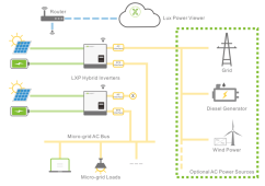
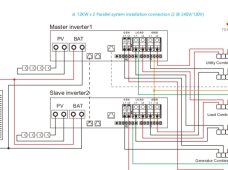
Only the primary hybrid inverter is connected to the grid from the above schematic. All slave inverters outputs are connected to the micro-grid through the EPS and any surplus power is back fed into the primary EPS to the 200A bypass relay that sends the surplus power to the grid? Since the slave hybrid inverters are rated at 12K, does that means that each slave can only feed the micro-grid with 12 K power each through the EPS? The 12K being the combined total from any combination of PV, batteries or AC couple? Can the primary hybrid inverter feed 200A bypass power to the grid from any combination of solar, batteries or AC couple? During a power outage the primary inverter is limited to 12K like the slave inverters? If you connect 18K of PV and 15K of AC couple power to a single inverter, you will never exceed 12K output, but you will have more hours of 12K when the sun shining? I just trying to understand the limitations, so I know better how to setup my system.
 
Last edited:
Hi @Not Aerosmith
try to have a quick answer first, before going to bed.
Only the primary hybrid inverter is connected to the grid from the above schematic.
1, Picture you used is not for LXP series, that is for our SNA series. but maybe somewhere we didn't update to a more accurate picture for LXP series. SNA is off-grid inverter, and LXP means on/off hybrid inverter.
All slave inverters outputs are connected to the micro-grid through the EPS and any surplus power is back fed into the primary EPS to the 200A bypass relay that sends the surplus power to the grid?
Can the primary hybrid inverter feed 200A bypass power to the grid from any combination of solar, batteries or AC couple?
2, No... The "200A" is the bypass current provided by the grid to the EPS, and it does not mean that the inverter can also feed back to the grid through the EPS with 12k power.
Since the slave hybrid inverters are rated at 12K, does that means that each slave can only feed the micro-grid with 12 K power each through the EPS?
3, If feeding to the grid(or micro-grid), yes the maximum exporting power to the grid is 12kW if solar panel or battery capacity is big enough.
The 12K being the combined total from any combination of PV, batteries or AC couple?
4, Yes, the inverter output can be multi-source on the DC sides. Do I understand you correctly? coz i don't understand why you mentioned AC couple here, is this 12k the grid output?
During a power outage the primary inverter is limited to 12K like the slave inverters?
5, 2 inverters can still work in parallel, so the limit will depend on how many units you connect in parallel. so here 2 in parallel, when outage, the primary inverter is limited to 24kW inverter.

If you connect 18K of PV and 15K of AC couple power to a single inverter, you will never exceed 12K output, but you will have more hours of 12K when the sun shining?
6, So this just depends on how big the battery you have, and make sure you understand the matter of "0.5C".

I just trying to understand the limitations, so I know better how to setup my system.

7. here, I would suggest you take a quick look at this video, introducing the working modes:

8, Manual book, the latest, refer to the attached one pls, to avoid confusion.


View attachment 149350
I just trying to understand the limitations, so I know better how to setup my system.
 

Attachments

  • LXP-LB-US 12k user manual(1).pdf
    7.2 MB · Views: 25
1684260425003.png

Each 12K hybrid inverter can only feed 12K to the grid or eps? Every additional inverter can feed another 12K to the grid or provide another 12K UPS. If you want to feed 200A to the grid or 200A UPS, you need need 4 inverters with adequate PV or batteries.

The wrong picture showed the batteries connected separately to each SNA inverter. Is this arrangement acceptable for the LXP? My batteries are 14.3k each and can provide the EPS with the max 12K to the micro-grid. If I connect both batteries to the same inverter, I am limited to 12K. If I connect each battery to a separate inverter, I now can handle 12K+12K from the batteries. The additional power might be helpful when starting a large load like my well.

Thanks for helping us to better understand these inverters and answering our questions. I appreciate you making the manual available and sharing the video.
 
Last edited:
@Eddie_Lux

What does "PV Grid Off" exactly do when it is enabled? Why do I get an "error code: 3" when I try to enable PV Grid Off?

What does "Seamless EPS switching" do when enabled as opposed to disabled? What would be a situation when it should be disabled?

LCD screen version 8, now requires a password to change the battery type. The old password from earlier versions to get into certain advanced settings doesn't work for LCD v 8. How can I get the new password?

Many of the settings have a blue "(?)" but when selected an error message appears without any help message. Why is that happening? How can I get a list of settings definitions and any other helpful tips on how to best use the settings?

Thanks.

1684256069447.png

1684256129314.png
 
View attachment 149432
The wrong picture showed the batteries connected separately to each SNA inverter. Is this arrangement acceptable for the LXP? My batteries are 14.3k each and can provide the EPS with the max 12K to the micro-grid. If I connect both batteries to the same inverter, I am limited to 12K. If I connect each battery to a separate inverter, I now can handle 12K+12K from the batteries. The additional power might be helpful when starting a large load like my well.

Thanks for helping us to better understand these inverters and answering our questions. I appreciate you making the manual available and sharing the video.
Good question @Not Aerosmith it's one of the highly frequently asked questions.
I would share some deatiled instruction regarding this.

1, Technically, 2 ways to connect in a parallel system are all available.
A) Only the master inverter connects the battery pack. (battery-shared enable )
B) Each inverter in the parallel system connects some battery. (battery-shared disabled)

2, However, we don't recommend the above 2nd way, namely to connect battery with each inverter in a parallel system.
Make sure you read this before using the 2nd way:

Parallel connection requires very balanced PV loads between the two LXP inverters, otherwise, if the PV loads are different, one battery may run out of power and shut down first, leading to system synchronization. It is recommended that customers use "battery shared" and connect the batteries together.
1684259061701.png

Connecting batteries of different brands is also not supported because batteries of different brands cannot be paralleled.
Parallel connection between a 20kWh and a 25kWh battery depends on whether the batteries support parallel connection with different capacity modes.

If both batteries are lithium-ion and have similar capacity, they can be connected in this way. However, there may be issues of uneven battery charging and discharging, depending on the PV and grid load size during parallel operation. This imbalance may lead to an earlier cut-off of one device during discharge when there is a demand to go off-grid, which weakens the overall load-bearing capacity of the system. Therefore, we generally recommend using the "battery-shared" mode.

Another situation is when lithium-ion and lead-acid batteries are mixed, the software does not currently support this application. This is because the synchronization of parallel operation can only choose to control one of the two based on either voltage or SOC. We will continue to improve the parallel synchronization part to make it suitable for more scenarios.

Definition:”Battery shared mode” refers to all battery inputs being aggregated on the bus, and each inverter is directly connected to the battery bus through wiring connections. Battery communication is only with the inverter master. However, mixing different battery brands is not supported in this mode.

3, Others,
I don't think you have 14.3kWh battery can provide continous 12kW output? Have you checked the max. current your battery pack can supply?
Read the parallel info from page 19 on the manual book.
As long as they are parallel connetced, the total output capacity can be doubled or times the qty you parallel connected.
You are welcome, hope others can get some useful info too from what you asked.
 
one of the two based on either voltage or SOC. We will continue to improve the parallel synchronization part to make it suitable for more scenarios.
Definition:”Battery shared mode” refers to all battery inputs being aggregated on the bus, and each inverter is directly connected to the battery bus through wiring connections. Battery communication is only with the inverter master. However, mixing different battery brands is not supported in this mode.
It sound like connecting all the batteries to the primary inverter is best, since all inverters are connected to the battery busbar. I was thinking that connecting all batteries to the primary inverter would have limited battery power to 12K only from the primary inverter. I didn't know the other inverters would still be able to use the power from all batteries. Thanks for the advice.
 
Last edited:
@Not Aerosmith , I *think* this diagram is how you want to do your install. Combine your batteries in parallel, then wire that into both inverters in parallel. The diagram doesn’t show the canbus cable, but that should go from the master battery to the master inverter. Make sure you have the inverters paralleled with each other properly, set them for “shared battery” as Eddie advises, and you should be good to go.

Edit: Oops, forgot to attach diagram.
 

Attachments

  • IMG_5681.jpeg
    IMG_5681.jpeg
    69.6 KB · Views: 20
@Eddie_Lux

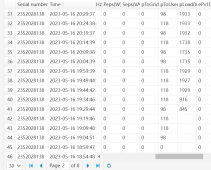
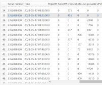
Something very strange happened yesterday at 19:19:46. All the prior pLoad values were cleared out (not 0, but actually just blank) and then the values started being reported way higher than the actual load. This morning, I started investigating what could be causing the problem and found that the CT ratio value had been changed to 1000:1. I wouldn't think that would affect the pLoad value, but I changed it back to 3000:1. At 08:03:02 it recorded a load over 10X higher than actual load, jumped around a lot and at 08:23:00 started recording 0 load and has been recording loads 10x since then. What is going on here?

1684350085938.png


1684350199502.png
 
thanks for sharing this here @Dcuste
most likely the CTs have some issue or are clamped in the wrong way.
Where's the CT's arrow toward? the correct way should toward the inverter.
And where you clamped the CTs? let's look into this. Thx
 
Status
Not open for further replies.
Back
Top