GridWorks Green Solar
Solar Innovator
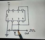
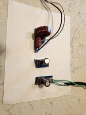
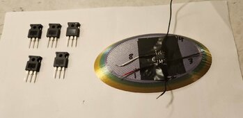
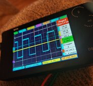
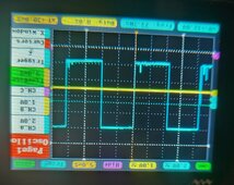
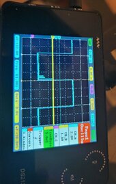
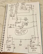
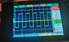
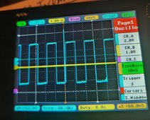
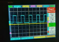
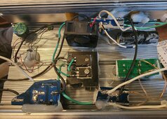
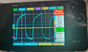
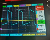
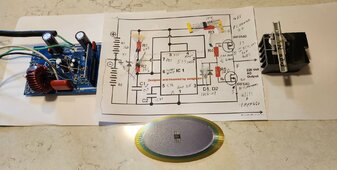
Going to stay focused on the build with the B1 & B2 input power source, I see a path to big power output naturally, also the test you requested shows a square wave before the LC circuit off the FETs expect the square wave out to nicely convert to pure sine especially since I have a nice ISO transformer already to experiment, expect transformer output sine wave to be rounded nicely.I have this,just do`nt know that to do
-https://www.next.gr/oscillators/Multiple-waveform-generator-circuit-diagram-l59906.html
View attachment 198364
-https://www.instructables.com/Grid-Tie-Inverter-V4-1/
View attachment 198363
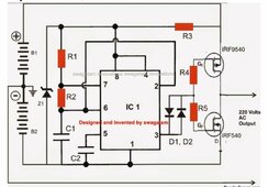
-https://makingcircuits.com/blog/h-bridge-inverter-circuit-using-ic/
DC for all
View attachment 198355
")
Best wishes

 )
)