diy solar

diy solar

New no battery pure sine wave solar power system with smart switchers.

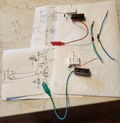
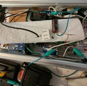
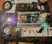
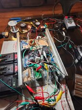
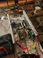
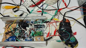
Making steady forward progress, tomorrow will start on the dual 12VDC power supplies.

When successful raising the input voltage should be no problem. Going to add a fly back diode to each Mosfet for inductive loads like motors to head off damage.

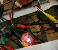
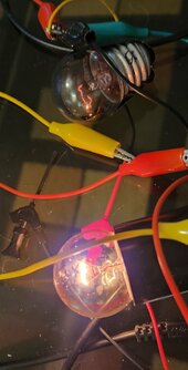
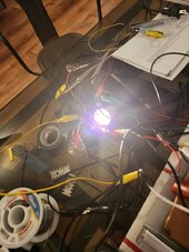
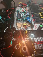
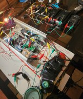
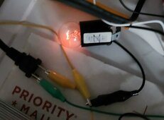
Can now run the inverter 24/7 off grid DC power supplies, all ready been on a couple hours now.

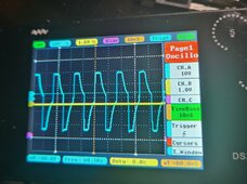
Definitely alot more stable.

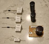
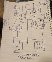
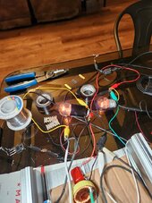
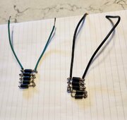
Ohms law shows 5.2 K resistor at 180VDC will only draw 34 miliampers of power falls well within the 150 miliampers allowed. I have super nice 12 volt zener diodes.

More tomorrow
 
Last edited:
Gathering parts needed for 12VDC floating power supplies for the new two FET inverter, need two power supplies right away.

Three resistors combined approximately 6.6 K ohms 5watts, 12Volt 5watt Zener diodes, overkill capacitors for filter and storage.

Success with the power supplies will allow 180VDC input from the solar panels.

Best wishes, more information later today.
 

Attachments

  • 20240327_060044~2.jpg
    20240327_060044~2.jpg
    156.6 KB · Views: 4
Parts soldered together ready to be installed in the two FET inverter, have found no examples online of the top left circuit example this inverter will be a one of a kind.

Two 12VDC power supplies and feed back diodes for the FETs.Building inverter to be motor friendly.

Electrical testing and more soldering ahead, more soon
 

Attachments

  • 20240327_150939~2.jpg
    20240327_150939~2.jpg
    188.9 KB · Views: 6
Floating power supply works on N channel FET just passed test on 42VDC, , must mount the circuit properly and proceed to the do the same for the P channel FET.

Stalled for the evening, will continue tomorrow, something stalling both 60Hz signals, FETs test OK, won't proceed with P channel 12VDC power supply till I get back what was working, think a full set of status lamps need to be added to the inverter so I can diagnose at a glance.

N channel 42VDC test worked twice in a row after a restart, fly back diodes are installed and working but may also be part of the reason things stalled suddenly, trust me I will get to the bottom of this, This is going to be a great inverter once I chase the bugs out.

Major step forward 💡
 

Attachments

  • 20240327_165314~2.jpg
    20240327_165314~2.jpg
    180.3 KB · Views: 11
  • 20240327_165321~2.jpg
    20240327_165321~2.jpg
    239.4 KB · Views: 11
  • 20240327_165350~2.jpg
    20240327_165350~2.jpg
    218.3 KB · Views: 11
Last edited:
Plagued with bad connections soldered and twisted, the dual 60Hz transformers got totally reworked this morning and now has LED output indicators, Like the foundation of a home if the signal is not solid nothing else works with the inverter.

Have P channel 12VDC power supply installed and it appears to be functioning but the module needs mounting and additional solder connections before increasing the operating voltage.

Right now everything seems to be functioning properly N and P channel both auto start, Silicone caulk needs to dry but both channels have already passed 42VDC test and both floating power supplies are working.

Could not be happier, just a short time till I attempt full input voltage on the new two FET inverter, needs a few more soldered connections.

High voltage testing P channel has passed 110 VDC input N channel passed 80VDC but started leaking at any higher voltage, suggesting some different gate resistors are nessassary, Pictures 3 and 4.😍
 

Attachments

  • 20240328_074145~2.jpg
    20240328_074145~2.jpg
    97.2 KB · Views: 5
  • 20240328_074153~2.jpg
    20240328_074153~2.jpg
    82.9 KB · Views: 2
  • 20240328_082055~2.jpg
    20240328_082055~2.jpg
    191.4 KB · Views: 2
  • 20240328_082656~2.jpg
    20240328_082656~2.jpg
    84.5 KB · Views: 2
Last edited:
More adjustments needed N channel but early results of P channel output says this is going to be a great inverter.

Starting all new diagrams P channel is rock solid, all previous drawings of P channel were sketchy because it was being invented.
1711632945212.png
 
Last edited:
Picture 175VDC input to the P channel getting 112 Volts out of the inverter, Perfect!

N channel even with changing out the gate close resistor 20K to a 9.1K still leaking anything above 80 Volts DC

Seriously thinking about if two P channel Mosfets can work this 🤔

Working the problems totally amazed what this inverter just showed me on the P channel.

More soon
 

Attachments

  • 20240328_135025~2.jpg
    20240328_135025~2.jpg
    319.4 KB · Views: 5
  • 20240328_135015.jpg
    20240328_135015.jpg
    138.6 KB · Views: 10
Last edited:
Still have not tested for single FET output through a ISO transformer.

Two P Mosfet inverter, I see no reason this would not work especially with two ISO transformers, with fly back diodes you may be able to extract usable power between the FET drains.

Preping for big transformer test.

Likely another million dollar idea 💡

More soon
 

Attachments

  • 20240328_191910~2.jpg
    20240328_191910~2.jpg
    132.8 KB · Views: 6
Last edited:
In uncharted territory here but exciting, Yes the big transformer makes a little noise from single FET output but it is also channeling big power, Shorted the output of transformer plenty of spark inverter did not blow at 65 VDC input, the transformer made a interesting growl noise only held the short a couple seconds.

Overdriveing the FETs right now but soon both channels will be tuned for best all around full sine power.

The thing seems tough as nails, needs more testing and research, already seen enough durability and power to know it will be very useful to someone.

So far low heat generation from the FETs, good news all around.

Have added lots of boost/filter capacitors to enhance operation but the basic design is very simple this will easily fit on a circuit board/kit that fits in your hand.

Testing everything attempt to extract usable power from the two output (L) feeds was not successful.

Picture cleaner diagram of two P channel Mosfet inverter,

More soon 😀
 

Attachments

  • 20240328_191910~2.jpg
    20240328_191910~2.jpg
    132.8 KB · Views: 4
Last edited:
Going to experiment with several N channel type FETs before trying the double P type inverter.

Maybe the 40N65 MOSFET will come to the rescue again, tested hooking the drains back together and the N FET got cooked by the P FET.

Mystery to be solved here. Any one have a suggestion to combine the two seprate synced signals into 120VAC power?

More soon
 
Last edited:
Setting up a test transformers output with two diodes in opposing directions to simulate the two outputs of the two P Mosfet inverter.

My current challenge is to combine the two seprate outputs back into full sine 120VAC power.

Not sure the best way to go about this, Any ideas?

Think the right set of capacitors could work as isolators and pass the needed power.
 
Last edited:
Have multiple tested good used N channel 40N65 MOSFETs to test in the new dual FET inverter.
Need three support components 10K resistor, diode, 5.6K resistor for the 40N65 FET

We are in the early stages of building this inverter, gut feelings your going to need a transformer of some kind to power multiple devices, if you just need to run light bulbs and heat elements we are mostly there already.

Several mysteries around early testing, the bulb is too bright for 112 AC/DC output measured on a analog meter, although the transformer made noises was able to push large amounts of energy through the big transformer.

Much to do in figuring out how best to get that synced energy back out usable.

Best wishes
 
Last edited:
40N65 FET is running at 66VDC, both P and N channels have full control.

Both running in sync, more testing tomorrow.

The recommended P channel Mosfet is still highly recommended, The N channel FETs killed all 5 of them IRFP460 and now testing the 40N65 MOSFET as N channel output.

More soon

Still more voltage testing ahead but right now in the picture both channels running smoothly at 66VDC, like twin jet engines but running opposite direction and 100% synced to 60Hz signal.

Floating 12VDC gate power FET supplies passed 175VDC input testing.

P channel has passed all testing.
N channel lacks full volts test.

Going step by step forward, just one big hurdle left in getting the power back out in 120VAC usable form.
 

Attachments

  • 20240329_191545.jpg
    20240329_191545.jpg
    186.4 KB · Views: 2
  • 20240329_191554.jpg
    20240329_191554.jpg
    209.6 KB · Views: 2
Last edited:
Both channels have passed 175VDC test, 40N65 FET bliss, ready for the solar panels now 💚

OK got the right voltage into the inverter, now to get 120VAC output, more tomorrow.

Big giant step forward the inverter is ready to do real work now, one more hurdle remaining.

Testing the N channel hard Picture.
 

Attachments

  • 20240330_004318.jpg
    20240330_004318.jpg
    182.7 KB · Views: 4
  • 20240330_004307~2.jpg
    20240330_004307~2.jpg
    112.8 KB · Views: 4
Last edited:
Have made substantial progress in combining the two synced output signals into one AC voltage, Using two power diodes where the P and N FETs feed the LC circuit. Right now if you reverse either diode you lose half the inverter output.

Voltage is back down to 24VDC and must test both sides again at the higher voltage.

Have eliminated one LC circuit and one light bulb from the inverter, sine wave power looks good going into the higher voltage testing.

Common netural/negative/ground are bonded the (L) outputs are not bonded together but output via the diodes to the pure sine output choke.

Working smoothly at 48VDC on each channel second/third Pictures.

The transformer I normally use to reduce the input voltage to the oscilloscope is being used for the optic coupler 60Hz signal, last scope output till I come up with something, blowing up the oscilloscope is out of the question can not do this type work with out a good scope.

More today
 

Attachments

  • 20240330_050856~2.jpg
    20240330_050856~2.jpg
    220.1 KB · Views: 11
  • 20240330_054152.jpg
    20240330_054152.jpg
    169.7 KB · Views: 8
  • 20240330_054218.jpg
    20240330_054218.jpg
    203.4 KB · Views: 8
Last edited:
Wow both channels passed 180VDC testing, looks like a home run ❤️

New inverter is a go for real world testing,

More later, need more and bigger diodes to test bigger loads. Dual diodes at the FET drains is working.

Second Picture: I hate paying for parts, took a little work and testing here are diodes that can handle 15Amps worth of current.

N channel 40N65 MOSFET and P channel IXTK40P50P for the win!

More soon
 

Attachments

  • 20240330_084113~2.jpg
    20240330_084113~2.jpg
    249.4 KB · Views: 2
  • 20240330_154139~2.jpg
    20240330_154139~2.jpg
    115.4 KB · Views: 5
Last edited:
It's great to see the progress that you've made. I can't wait to see the finished product. With this new innovation can the system be grounded? I know that was an issue with the original setup.
 
It's great to see the progress that you've made. I can't wait to see the finished product. With this new innovation can the system be grounded? I know that was an issue with the original setup.
It is still up in the air, I will eventually sacrifice the test card board based inverter to find out for sure, I bet it fails but if not the path to sun power gets a whole lot less complicated.

This inverter is going to easily fit on small circuit board that fits in your hand. Around $100 in quality parts.

Best wishes
 
15amp diodes for the FET drains installed and passed operational electrical testing.

Unit continues to power up correctly every time, going to initially fuse at 5amps need 7amps to run the quartz tube heater on High, Looking forward to real world testing the inverter.

More soon
 

Attachments

  • 20240330_154139~2.jpg
    20240330_154139~2.jpg
    115.4 KB · Views: 3
New two FET inverter is being powered by dual 180VDC solar arrays this morning.

Everything is fused at 5amps for safety, really excited several important measurements to come, cannot wait to see inverter output AC voltage.

Bulb has just started to burn, so far so good, small heater is also connected 250 watt low 500 watt high.

Sun up is around 9AM est.

Lots of testing ahead, more soon.

Best wishes
 

Attachments

  • 20240331_071914~2.jpg
    20240331_071914~2.jpg
    158.7 KB · Views: 2
  • 20240331_071907~2.jpg
    20240331_071907~2.jpg
    494.5 KB · Views: 2
Last edited:
Back
Top