diy solar

diy solar

Connecting Pure Sine Wave off-grid inverter to home office on grid

matttelz

New Member
Joined
Dec 5, 2022
Messages
25
Location
Washington DC
Hey all,

I'm planning on getting an off grid inverter 1200w to power my small office. I work remote so I'd like to power my office entirely off grid. Can I connect my inverter with the wonderfully safe male to male 120v cable to an outlet in my office with the breaker at the box switched off?

I understand that I can't connect an off grid inverter to the grid. I'm hoping I can just plug it into an outlet and power all the outlets on the circuit. The big thing is having it off at the breaker so it doesn't connect to the grid.

I did some research and the concern is if the neutral is tied into the ground. So I need to check for that?

Option 1: ShockFlo 1000 watt Pure Sine Wave Power Inverter, 1000W Off-Grid Solar Power Inverter 12V DC to 110V AC Built-in USB Ports Remote Controller and LCD Display, Converter for RV Home Truck https://a.co/d/fajtqlW
Option 2: Power Inverter Pure Sine Wave 1200 Watt 12V DC to 120V with Remote Control Dual AC Outlets and USB Port for RV Car Solar System Emergency https://a.co/d/4P5wFjO

Planning on getting 100-200ah battery to power this with eventual solar to power it entirely off grid hopefully.

I have a small little 24ah system with 300w inverter and it powers my work station just fine but only for about 4 hours...
 
with the wonderfully safe male to male 120v cable to an outlet in my office
You do know this is called a suicide cord for a reason, right?

 
You do know this is called a suicide cord for a reason, right?


Yes. I took it 1 step further when I was a kid at my parents house. I wired a Y for an extension cord to a 240v air compressor. Plugged in each 120v plug in an outlet in the house on separate legs from the breaker to make 240v. Worked great, just always knew there was a live prong when plugging them both in. Thankfully never slipped. Lol
 
If you decide to do this, please report back to us in the following forum:
 
OK all. Quick update.

I ended up getting the Giandel 1200W Pure sine wave inverter. Got it for a decent price, $130 out the door...

I also purchased my first set of solar, 2 100w panels and a cheap PWM charge controller (I'm not pulling a lot of solar so the cheap PWM was probably my most economical route). I'm planning on modding the controller with additional heatsinks since I've read some of them can burn down depending on the input wattage. I also ended up getting the DJLBERMPW 100AH lifepo4 battery. I'm waiting on that to deliver this week along with some additional wire for solar and some battery cables.
I should have everything by the end of this week and have it hooked up next week.

I'll probably go the extension cord/power strip route...lol
 
So been playing around with my setup over the weekend. I did some poor math and research and undersized my solar wire WAYY too much. Ended up going with 14awg wire and I'm currently pulling around 10A in full sun, planning to add 1 more panel. Based on my calculations I'm getting a pretty significant voltage drop. The wire is actually warm at charge controller.... Purchased some new 8AWG wire instead so hopefully that will eliminate that issue.
I also picked up a watt meter to monitor my solar input. I'm working on getting proper ring terminals and connectors for my solar so its easy to connect/disconnect using XT60 connectors.

I'm looking to build a stand/frame for the 3 panels so they can fold and be stored away along with pulled out and arranged to gather as much sun as possible. I'd love a solar tracker but I don't think that's going to be possible ATM.

The Giandel inverter is working well. Handles everything in my office just great, tested it on the fridge/freezer and toaster with no issue. Pulled 850W with no issue.

Battery is holding up great. I'm planning on mounting a plate to the battery side where the inverter will be mounted to along with the solar charge controller so everything is contained right at the battery.

I did size the battery wire correctly. Ended up getting stranded copper 2AWG wire for the inverter so that's good!

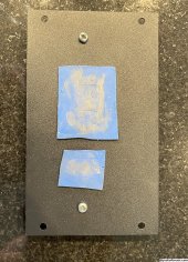
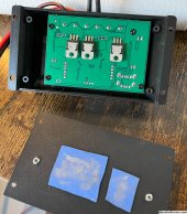
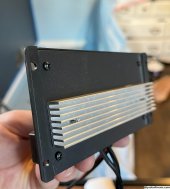
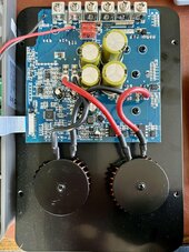
I modified the solar charge controller since it was getting quite warm. Fixed the crappy thermal pad along with adding a heatsink to the back. Should easily be able to handle whatever I throw at it now. Charges the LIFEPO4 battery just fine despite some people saying otherwise.

IMG_0143.jpg
IMG_0146.jpg
IMG_0147.jpg
 
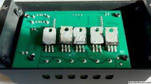
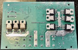
So the solar charge controller (30A version) caps out around 215w and starts to thermally throttle. I suspected it has something to do with the limit of the mosfets just exceeding their current limitations. So I ended up getting another solar charge controller, this time with a different layout and gave that a try. The 60A controller had 5 mosfets but unfortunately wasn't programmed to charge the lifepo4 battery properly. So I ended up desoldering the mosfets from that one controller and adding them to the existing controller. Walla, no issues and I'm well past 240w on the controller with no issues so far.
I probably need a new thermal pad for it but it'd actually be better if the entire back of the controller was one large aluminum heatsink so I may shop around for one that might fit...
I'm guessing each mosfet can handle about 5A each so the original design was limited to about 15A which sounds about right. So now I should be good for around 25A now. IMG_0307.jpeg
 
Maybe I am just to new to all of this and do not realize how interchangeable some things are. But you should get a sign that for you door that says "Keep out, evil mad scientist at work"..."p.s. beware the leopard"... everything is working but beware the danger
 
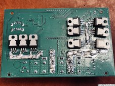
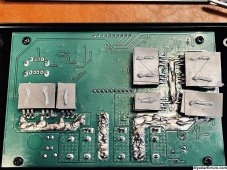
I received my 3rd controller now. Did alot of research and aparently there's a larger version of these pwm controllers that actually has a metal heatsink on the back.. The new controller is very nice and actually has 9 fets so definitely should be an upgrade. The soldering was very poor so I ended up beefing up the traces and fixing some of the solder joints. Works like a charm. It's coudy and rainy here so will need to wait for a sunny day to see what sort of heat it generates.. I like this one much better because it can easily handle my 8awg wires too.
Stock:
IMG_0446.jpeg

Beefed up traces:
IMG_0449.jpeg

With heat tape and some thermal paste:
IMG_0451.jpeg

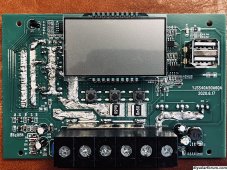
Front is also Beefed up:
IMG_0450.jpeg
 
I received my 3rd controller now.
Can you share a pic of what the front of the SCCs look like? I have a bunch of them and always wondered what they look like inside and what it would take to fix or improve.

Curious as to why the middle leg of feds is beefed up on the 6 mosfetts (pictured on right) vs the left leg on the 3 pictured on the left.
 
.
Navy solder school speaking here. The was board conformal coated to prevent moister and corosion. If you wanted to beef up the runs that should have been removed first.

Second, the correct way to do that would have been to clean all the old solder off and lay a thin copper strip on it and solder that down. But, unless they used reject PCB the original run should be sufficient to carry the current.

Either way, were it me I would clean all of that mess off and make nice clean connections. If for some reason some of the runs have come loose from the board then tack down a wire to the buss and the hole for the fet wrapping the wire around the leg. Figure the current and use a wire capable of handling it.

Once you are all done clean it up and get a bottle of brush on conformal coat and to everything but the backs of the fets.

The current job of solder would have earned me extra duty and perhaps being sent back to start solder school over or simple revocation of my solder card.
 
Yes. I took it 1 step further when I was a kid at my parents house. I wired a Y for an extension cord to a 240v air compressor. Plugged in each 120v plug in an outlet in the house on separate legs from the breaker to make 240v. Worked great, just always knew there was a live prong when plugging them both in. Thankfully never slipped. Lol

The exposed pins are only hot if load is connected (and on.)

I did similar at work - 120/208Y came to lab, and each bench got 120V. We had products to work on that needed 240V or 208V, so I briefly used a "Y" cable. Then, especially to protect others, I made one with a box containing two relays. Each 120V plug completed circuit to outlet, so no power at outlet unless both plugs connected, and no hot pins.

I labeled it "Not a Suicide Cord".

Could be, once connected with a load, it would remain latched on when one unplugged. I think I tied neutrals together, should not have since outlet wasn't using neutrals.

So been playing around with my setup over the weekend. I did some poor math and research and undersized my solar wire WAYY too much. Ended up going with 14awg wire and I'm currently pulling around 10A in full sun, planning to add 1 more panel. Based on my calculations I'm getting a pretty significant voltage drop.

How long is that wire? What voltage drop did you calculate?
PV panel will drop from Voc to Vmp. with an MPPT charger. It will drop to Vbat with PWM charger.

The wire is actually warm at charge controller.... Purchased some new 8AWG wire instead so hopefully that will eliminate that issue.

But not warm elsewhere. 10A through a wire with 25A ampacity (in bundle of three), 35A ampacity (single conductor in free air) isn't going to get very warm.

Bad contact or heat generation inside controller will get warm. Wire may serve as heatsink or transistors.


I modified the solar charge controller since it was getting quite warm. Fixed the crappy thermal pad along with adding a heatsink to the back. Should easily be able to handle whatever I throw at it now. Charges the LIFEPO4 battery just fine despite some people saying otherwise.

What PV panel voltage rating? What battery voltage?

Since it switches on/off, I don't expect PWM to get particularly hot, but I suppose it would be designed to the edge, just to be cheap.
Higher voltage PV panel would put more stress on PWM, not sure if it causes extra heating (switching through an inductor would), but it is extra voltage stress. PWM will have a spec for PV panel vs. battery voltage.
 
Panels are 3 in parrallel, they're about 23.1v no load. I'm only talking about maybe 275w on their best day with 3-100w panels.

I didn't see any conformal coating but I also didn't do a ton of prep ahead of the modifications.

I'm just on a small 12v battery setup for now. 100ah. Looking to go to 200ah someday soon hopefully.

I only have 10ft of wire from the panels to the controller but will likely need to add another 10ft once I get my solar tracker built.
 
Do yourself a big favor and get a modest MPPT charge controller. Connect the 3 panels in series and you will have virtually no voltage drop. You will collect over 30% more total energy each day.

Why dos it make such a big difference?
I made this mistake in my math early on as well. Your "100 watt" panels have a maximum power voltage closer to 18 volts, probably around 5.5 amps in perfect noon day sun. When the PWM controller connects them to the battery, the voltage is dragged down to 13.8 volts, but the current stays about the same. So under the perfect conditions, you only can ever get 13.8 volts x 5.5 amps = 75.9 watts from those 100 watt panels. And most of the time, it will be even worse than that. At best, in perfect sun, you will never top 17 amps with your 3 x 100 watt panels in parallel to the PWM controller.

Run the panels in series, you get 18 x 3 = 54 volts, any 100 volt MPPT controller will take that. The current stays at just 5.5 amps, so no big loss issues, even at #14 or 12 awg wire. But now that perfect noon time sun can make 100 x 3 = 300 watts, and the charge current at 13.8 volts is now closer to 21 amps, even factoring in some losses.

That will likely be a cheaper upgrade for more power than a tracking system.
Ah, now it makes sense. I always wondered why the voltage from the panels drops from 23v to whatever the battery voltage is, ~13V on the solar side even before the PWM controller...I guess it also makes sense when I see the battery voltage increase, I end up getting a higher charge wattage due to the higher voltage but constant current.

I already have everything for my solar tracker so the expense was pretty minimal so at some point I'll look into an MPPT controller but for now, since my setup is soo small, I can probably fair the losses for now.
 
I'm looking at getting the pow-keeper1240 mppt charge controller from PowMr. Love the name. Lol

I think it's authentic but not really sure since on their website directly it's like $30 more expensive. I may give it a go on ebay and if it's fake ebay should take care of me. Looks like it should be able to handle 400w easily with my application at 12v so even if I add a panel I should be good.
I'm maxing out around 220w peak so getting upto 300w would be nice and possibly 400ish with a 4th panel would be even better. My plan this year is to get at least 1 or 2 more 100ah batteries as I can burn through 1kw pretty quick...

I've got a few house projects ahead of the solar upgrades so once I have an idea of those costs I'll be in a better place for my upgrades. Also year end tax will give me an idea of what I'm getting back tax wise on my investments...thatd be a huge plus!
 
I would have just built Will’s hand cart system and done away with the project. Too much time and effort otherwise (but that’s just me).
 
I would have just built Will’s hand cart system and done away with the project. Too much time and effort otherwise (but that’s just me).

Yea, I'm definitely taking my own path I guess...

I'd like to have a better way of monitor my battery SOC... thinking of getting this hall sensor monitor: https://www.amazon.com/ECO-WORTHY-B...8828621&sprefix=eco-worthy+hall,aps,80&sr=8-2
Looks like a bunch of people have stated some issues with hall sensor monitors being inaccurate under high amp draw? I don't think I'd be exceeding more than 120A since my inverter is a 1200w inverter anyway...
I'm nearing tax season so I should have some good idea what type of EPA tax credit I get on my solar components. Once I have a better idea of than I plan to increase my solar with 1 additional panel and probably 2 or 3 more batteries. Ideally a 4-5kw battery bank should be sufficient for my needs along with ~400W of solar....
I plan to eventually get around to mounting my solar on the side of my home with bracketing. I have a brick home so it shouldn't be too terribly difficult. Not on the roof since my roof is east/west facing. I have a nice balcony that I can get direct South sun with little to no obstructions.
 
IMG_0808.jpeg

Not sure what I'm looking at but it seems to be working good. I was able to wire it up and program it for lifepo4. We shall see how much it tops off the battery. Had brief sun this morning and was getting around 250w from my 3 panels around 10am before the clouds and rain rolled in... So I'm already exceeding what my pwm controller could do on a clear day...

Design of the controller is a heck of alot beefier than the cheap pwm one. I guess that's the difference between $15 and $55.

I definitely need more battery capacity compared to more solar. I'll likely run out of battery with two consecutive days of clouds using the battery for my desk with 2 laptops and 4 office lights...
Later this week should be sunny so excited to see how close I can get to 300w input with my 3 panels...
 
Back
Top