diy solar

diy solar

New no battery pure sine wave solar power system with smart switchers.

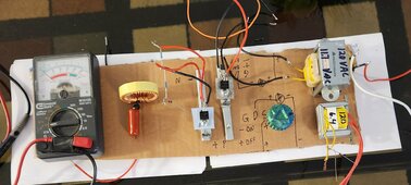
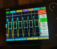
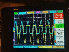
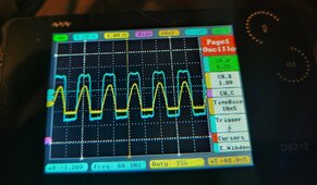
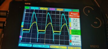
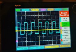
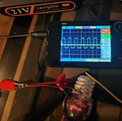
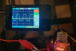
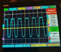
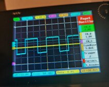
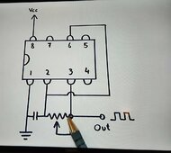
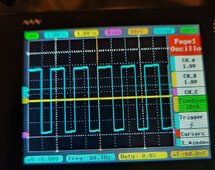
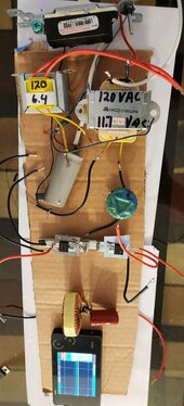
See a path to actually make this inverter work. With the right capacitors on the555 timer it is getting 60 to 61Hz, The LC circuit can work all the way down to 50Hz so if I put the drift between 59 and 60Hz it's a win.

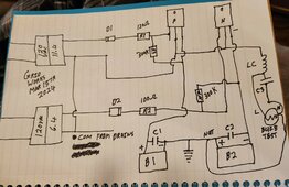
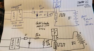
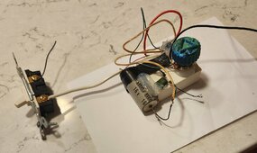
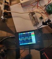
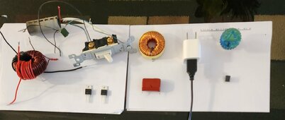
Found four things wrong with the original circuit diagram, wrong voltage FETs, B2 power source was inverted and you will need two gate isolation transformers to switch high voltage.
Also the power supply for the 555 is Wrong will need a stable 5VDC power supply.

Just a short time till it will actually work.


Best wishes
 
Last edited:
Flooded batteries needed 1/2 gallon of distilled water all 4 deep cell batteries passed electronic testing, Equals about 3 to 4 hours of you really did not notice grid power went off and have to break out a generator.

Both systems look ready for summer, after heavy spring pollen I will pressure wash the solar panels.

Information added to some of the previous post.

More soon
 
Last edited:
After some yard work today I plan to solve the gate isolation issues of the new two FET inverter and get pure sine output, I have 6 of the ten to one used isolation transformers and several ring core transformers.

Watched probably the best YouTube video so far on winding your own Mosfet isolation transformers out of the magnetic ring cores and actually demonstrating them working.

Have high hopes to solve this, Have yet to see a P and N channel side by side FET example, wish me luck.

More later today.
 
Getting parts ready for second flip test inverter featuring fresh DIY dual output Mosfet gate isolation transformer, each output is 8 turns per a YT video,1000watt LC circuit for pure sine, 5VDC USB power supply for the 555 timer. Project rules call for a transformer for the USB power supply but the FET ISO will have the same effect in keeping any bias separated.
After I get it running and conduct Many test this is the one that will be connected to earth ground per the diagram and see if it servives, If it doesn't explode or short out it can reduce the cost of turning sun to 60Hz AC power.

Main focus gain full control of the FETs, get it right the first time diagram and parts list, once working get the big flip inverter working in the same way.
Last test will be the earth ground test.

Once I can repeat the build work will begin on a dual side circuit board kit.


More soon 😀
 

Attachments

  • 20240314_151548~3.jpg
    20240314_151548~3.jpg
    162.7 KB · Views: 5
Last edited:
As it sits right now not passing enough power accross the DIY ISO transformer to properly switch the gate.

I have a small 120VAC to 6.4VAC transformer that falls into the good range for FET triggering grid 60Hz signal, Need two of them one for P and N channel Mosfet.

Easy way to leap frog forward with testing and FET trigger.

Working on it
 
Early look at new test inverter, FETs mounted and leads attached,

The two transformers will be for isolation and 60Hz signal to the P and N channels.

Focus of this testing will be getting the P and N MOSFETs to sync @ 60Hz, The LC circuit will make pure sine up to 1,000 watts, Much more testing ahead after it works.

Multiple replacement parts if things go wrong will be fused for 5amps max.

Going to cheat with the 60Hz transformers but will return to 555timer 60Hz after getting forward progress.
Maximum gate rating is + or - 21 volts.

Taking a break now more soon.
 

Attachments

  • 20240315_121544~2.jpg
    20240315_121544~2.jpg
    111.8 KB · Views: 12
Last edited:
Nice,
So, LC circuit will make pure sine without transformer-Great(y)
Are you going small power and whan up?
 
Nice,
So, LC circuit will make pure sine without transformer-Great(y)
Are you going small power and whan up?
Yes after verify isolation raising input voltage till 120VAC output is achieved is next.

Just a bit more time, put diodes on isolation transformers output I can produce solid forward humps or dips on the oscilloscope 60Hz. Looks good I just have to bring it all together.

Just caught a big mistake because of the FET type the mounting, one FET must be moved to a separate metal bar because right now they electronictricly bonded together, nice catch before I cook the FETs.

More soon

Excited 😀
 
Last edited:
Nice,
So, LC circuit will make pure sine without transformer-Great(y)
Are you going small power and whan up?
Yes after verify isolation raising input voltage till 120VAC output is achieved is next.

Just a bit more time, put diodes on isolation transformers output I can produce solid forward humps or dips on the oscilloscope. Looks good I just have to bring it all together.

Small improvement FETs mounted to separate heat sinks.

Excited 😀
 

Attachments

  • 20240315_145415~2.jpg
    20240315_145415~2.jpg
    251.8 KB · Views: 1
Output from both transformers on dual trace scope not what I expected should look more like a sine wave between blue and yellow traces, solid 60Hz signal 58% duty cycle.

I will keep at it, any suggestions will be appreciated. Using one diode per transformer.

Think I need to swap one of the transformers polarity.
 

Attachments

  • 20240315_155033~2.jpg
    20240315_155033~2.jpg
    201 KB · Views: 9
Last edited:
Big step forward swapped the input to one of the transformers.

Hot off the press second Picture not yet tested of what I am going to test next.

I can make this work! Must figure out how to control the P channel. Attempt to just finish it did not work, step by step diagnostic testing required to make it run, good news it is not that complicated to trigger a FET. A couple potentiometers installed in the driver circuit should help zero in on the correct settings, Love the oscilloscope output especially with comparing two slightly different transformers. Several steps forward today.

So close so very close.
😍
 

Attachments

  • 20240315_160907~2.jpg
    20240315_160907~2.jpg
    251.8 KB · Views: 2
  • 20240315_171622~2.jpg
    20240315_171622~2.jpg
    234.7 KB · Views: 9
Last edited:
Things are going to slow for a bit as I figure this out, Two problems getting the switching bias correct for both channels when the drains are connected together and sine wave over lap between the blue and yellow traces on the oscilloscope against the rules to be on at the same time (Short circuit the FETs).

This is not what I am best at (circuit design) Watching a ton of YouTube videos on Fet drivers, already know IC driver chips exist that simplify this process.

Invite anyone to help, have yet to see an example of a P and N Mosfet with drains connected, The original circuit during the first 9volt DC test actually operated but acted like a bias was affecting the 555 timer circuit.

Working on it, More soon
 

Attachments

  • 20240315_160907~2.jpg
    20240315_160907~2.jpg
    251.8 KB · Views: 1
Some progress, Dual trace yellow is 60Hz signal from gate drive transformer with diode, Blue is output signal from a N channel Mosfet. Next P channel.

YT videos on tesla coils FET driven show capacitors are the isolators in the circuit.

Trigger signal looks good, Mosfet output looks amazing. Remember me talking about a single FET inverter?
That signal sent to a LC circuit will produce pure sine power. At some point I will test this idea.

Final working configuration matching one example from YT video that has a few more parts to enhance trigger signal bias.

Single N channel Mosfet passed 9 volt test. Hooked up LC circuit out of curiosity not a sine wave but compared to the before picture the tops of the blue waves are rounded. Bet it will run light bulbs💡

Keep it simple is still working.

More soon
 

Attachments

  • 20240316_183817~2.jpg
    20240316_183817~2.jpg
    287.8 KB · Views: 1
  • 20240316_210437~2.jpg
    20240316_210437~2.jpg
    237.2 KB · Views: 2
Last edited:
18VDC running test lamp and good square wave output from FET. Good 60Hz signal

Baby steps, passing 18volt test, so far the driver circuit is good. Next step 21volts.

Third picture 😀

Passed 21VDC test, gate leaking when 60Hz signal is not present. Suggest a few part changes in order, Baby steps.

Picture number four:

Resistor R1 300k in drawing is now 15K and closes the gate at 42 volts with no 60Hz signal, 42 volt test has passed.

Making forward progress. 90VDC test gate leaking when no 60 Hz signal more parts changes needed but responding OK to rapid increase in test voltage.

Bulb now burns very bright last picture.

More soon
 

Attachments

  • 20240317_072328~2.jpg
    20240317_072328~2.jpg
    143 KB · Views: 4
  • 20240317_072332~2.jpg
    20240317_072332~2.jpg
    254.6 KB · Views: 1
  • 20240317_074018~2.jpg
    20240317_074018~2.jpg
    160.6 KB · Views: 7
  • 20240317_083221~2.jpg
    20240317_083221~2.jpg
    190.3 KB · Views: 4
  • 20240317_085447~3.jpg
    20240317_085447~3.jpg
    149.1 KB · Views: 4
Last edited:
Change in direction, parts need to be ordered, opto couplers are the answer to high voltage control. As the voltage increases the gate is harder to switch and leaking when it supposed to be off.

Optical isolation is tiny and it works, YT example switches 200volts N channel Mosfet no problem, Basically a 60Hz flashing LED from a 555timer controlling the Mosfet. Circuit is powered from solar 555 timer will be USB 5VDC supply.

Optocouples ordered $9.99 for 20, The main parts list and diagrams are about to change in a big way, smaller less expensive parts that give you big FET control and isolation 😀

Personal diagrams P and N MOSFET control up to 42VDC. The D2 diode for the P FET example needs to be flipped over.

More soon
 

Attachments

  • 20240317_114635~2.jpg
    20240317_114635~2.jpg
    249.3 KB · Views: 1
Last edited:
Proof of P channel 60Hz Mosfet output. Updating personal diagrams. Working up to 42VDC from transformer based 60Hz signal.

Two days to get opto parts and make new control circuit, very happy so far steady progress toward a home run.

Still have to figure out shared drains off the P and N MOSFETs and shared netural from the B1 B2 solar panels.

Enough functionality right now to build an inverter that uses a step up transformer for output, Looking for direct drive solar 150 to 180VDC solar input.

Looking good.


More soon
 

Attachments

  • 20240317_112441~2.jpg
    20240317_112441~2.jpg
    255.3 KB · Views: 1
Last edited:
Newest best attempt at the 555timer, silicone caulk must set before testing it.

Unit will be powered by 5VDC USB power adapter.

Really hope I am done killing the parts but just in case have four more new ones out of 10 to start with.

This timer will only power two LEDs inside the optical couplers one forward and one reverse to pick up the entire square wave signal to trigger the FETs, opto couplers have an isolation value of 10,000 volts. Awesome.

Making forward progress.

More soon
 

Attachments

  • 20240317_193954~2.jpg
    20240317_193954~2.jpg
    228 KB · Views: 6
Last edited:
Testing new 555 timer, perfect!

USB powered 5VDC, Exact 60Hz square wave, will only be driving two LEDs one forward and one reverse in the opto couplers.😀

Adjustment of the brightness of the LEDs will be a easy fix for blue/yellow phase (on) overlap dimming the LEDs will retract them away from the center line over lap and prevent a on short of the FETs.

The drift is between 59 and 60.4 Hz ❤️

The work I did yesterday will pay off for years to come, the large capacitor runs it for an additional 30 second after the switch is off, Very stable square wave as compared to other 555 timer configurations for 60Hz signal.
At some point the adjustment knob will be replaced with a single resistor.

I smell victory ✌️
 

Attachments

  • 20240318_110444~2.jpg
    20240318_110444~2.jpg
    127.4 KB · Views: 2
  • 20240318_110440~2.jpg
    20240318_110440~2.jpg
    207.7 KB · Views: 2
Last edited:
Ultimate cheat sheet if you want 50Hz or 60Hz timer signal from a 555timer for power production.

Put in the time to do this properly and get rid of the 500K potentiometer.

Simple configuration 555timer picture below using 2A154k small green ceramic capacitor, 83K for 60Hz signal, 151K for 50HZ signal. 5VDC power supply.

Beautiful square wave output. Put a filter capacitor on the main 5VDC supply.

This works stable, resistors used:

60Hz 30K+30K+20K+3K=83K ohms.
50Hz 100K+51K =151K ohms.

Testing revealed putting a load on pin 3 output lowers cycle hertz, for example one LED lowered output to 40Hz, you may need to lower the resistance to compensate depending on how you use the pin 3 signal.

Soldering in 60Hz next and final testing.

Soldered in and works great Pictures

Best wishes
 

Attachments

  • 20240227_230049~2.jpg
    20240227_230049~2.jpg
    183.5 KB · Views: 8
  • 20240318_153956~2.jpg
    20240318_153956~2.jpg
    185.6 KB · Views: 6
  • 20240318_153952~2.jpg
    20240318_153952~2.jpg
    265.7 KB · Views: 1
Last edited:
Purchased two of the $20 P channel 500 volt 40 amp FETs, thought I damaged the 21volt gate on one of them during the first double 21VDC battery test on the big inverter. Swapping out the part with a new one.

Good news just tested the older P FET and it still passes for new in operation.

Opto couplers due in tomorrow.

More soon 😀
 
Back
Top