diy solar

diy solar

New no battery pure sine wave solar power system with smart switchers.

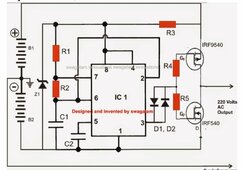
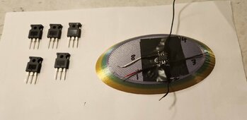
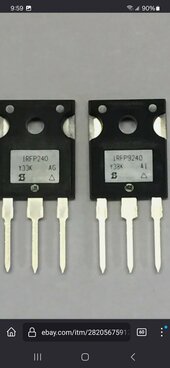
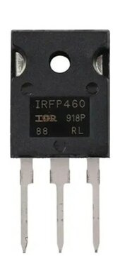
Found a nasty start problem with the flip flop inverter, Diagram clearly shows 220VAC output but the main FETs only have a 100 volt max rating on the drain per the spec information.

Still going to proceed as > 98 volts pure sine will run most electronic devices and can upgrade the FETs for more volts/amps after I get pure sine working correctly.

Best wishes, more later
 
Need help with selecting the proper set of MOSFETs or Transistors for the push-pull/flip-flop inverter, need 200 volts 15 Amp switching of DC, need fast switching for 60Hz power.

IRF9540 and IRF540 19Amp and 100 volts maximum, The IRF9540N and IRF540N have 33amps and the same 100 volts maximum limit.

One data sheet says easy to parallel but doesn't provide any information on how this might be done, also doubt it changes the 100 volts maximum limit.

The above mentioned parts received a ding for constant drain current when operating at near maximum voltage in other words the parts run hot even when not doing much work (I certainly hope to do better) baby steps till I get it working full sine.

Please help, switching between a forward DC solar array and reverse DC solar array to make 60Hz AC power.
 
Last edited:
Starting to find P channel and N channel MOSFETs in the 200 volt range.

Looking for a matching pair, Could still use help in the search IRF640N is a 18amp 200volt N channel, Looking for a matching pair of N and P channel components.

IXTK90P20P is a similar P channel 200 volt Mosfet but not matching.

Surprised to find 900 volt FETs available.

More soon, expected ordered parts to arrive Monday, still have a EGS002 new in the bag for possible as a driver CPU, lots of new and used parts for testing.

Found something sold as a matching pair IRFP9240 P channel and IRFP240 N channel. Although the P is only rated at 12 Amps and the N channel is 20amp both 200 volt ?
 

Attachments

  • Screenshot_20240222_215922_Firefox.jpg
    Screenshot_20240222_215922_Firefox.jpg
    46 KB · Views: 1
Last edited:
Never stop to improve,but only way,Best
Looking for the simplest best way to make pure sine power with two main Mosfets and then I am going to make high quality kits with printed circuit boards and free information so you can make your own.

12amps is enough for a start system but planing to X2 X4 on amp output. Still looking for the correct set of MOSFETs.

Must have 15Amps for level 1 inverter output.

More soon, best wishes
 
Last edited:
Found a set of MOSFETs that might just work not matching but exceeds all requirements needed.

IRFP460 BF N- channel 500 volt 20amp MOSFET
IXTK40P50P P- channel 500volt 40amp

Makes me happy to find parts that can exceed 15 amps and 180 volts 60Hz.

Best wishes
 

Attachments

  • Screenshot_20240223_145207_Firefox~2.jpg
    Screenshot_20240223_145207_Firefox~2.jpg
    21.6 KB · Views: 3
  • Screenshot_20240223_144003_Firefox~2.jpg
    Screenshot_20240223_144003_Firefox~2.jpg
    18.5 KB · Views: 3
Last edited:
Basically the two photos show what I am going to attempt with different parts, the left diagram will get bigger much better FETs and storage capacitors for high voltage DC input from the solar panels to better handle a surge, the photo on the right will be the same output LC filter circuit as the the one found on the project power board.

Interested in the earth ground between B1 & B2 if the project system was grounded in that manner the board would fail.

Interested in the pure sine wave we are going to get.

Bet one configuration or the other is going to provide big efficient direct drive power production with the inverted solar PV arrays, curious about what solar PV DC input voltage will result in 120VAC output. Output ISO transformer will be located where the oscilloscope is located.

Going to reconfigure a bad project power board for the LC output circuit, FET mounting and input DC capacitors, the 555 timer IC will be glued to a second board and configured for 60Hz signal. Once I get it right going to make a printed circuit board that makes it easy to build and mount in a standard inverter case.

Excited to see it work might have to design a soft start to prevent surge problems.

Best wishes
 

Attachments

  • Screenshot_20231109_133354_Firefox~3.jpg
    Screenshot_20231109_133354_Firefox~3.jpg
    78.5 KB · Views: 3
  • 20240205_205305~2.jpg
    20240205_205305~2.jpg
    208.3 KB · Views: 4
Last edited:
I have this,just do`nt know that to do :)
-https://www.next.gr/oscillators/Multiple-waveform-generator-circuit-diagram-l59906.html
Multiple-waveform-generator-circuit-diagram.png
-https://www.instructables.com/Grid-Tie-Inverter-V4-1/
General_Schematic2.png
-https://makingcircuits.com/blog/h-bridge-inverter-circuit-using-ic/
DC for all
UPS220.jpg
 
Why not 40N65?
I see another mix also.Best
See no reason why the 40N65 would cause any problems in the role of the N channel MOSFET in the new inverter, note the 40N65 requires three support components not shown on the left diagram, going to build on the original design then expand quickly (Going to build two expect one to fail quickly)

More soon
 
I have this,just do`nt know that to do :)
-https://www.next.gr/oscillators/Multiple-waveform-generator-circuit-diagram-l59906.html
View attachment 198364
-https://www.instructables.com/Grid-Tie-Inverter-V4-1/
View attachment 198363
-https://makingcircuits.com/blog/h-bridge-inverter-circuit-using-ic/
DC for all
View attachment 198355
Going to stay focused on the build with the B1 & B2 input power source, I see a path to big power output naturally, also the test you requested shows a square wave before the LC circuit off the FETs expect the square wave out to nicely convert to pure sine especially since I have a nice ISO transformer already to experiment, expect transformer output sine wave to be rounded nicely.

Best wishes
 
With a 50% duty cycle on the alternating solar arrays the in between voltage spikes will build up in the capacitors for an extra punch of output energy.

The effect should be awesome!
Also this voltage boost will excite the full sun panels MPPT effect for more energy.

I fully expect this to work after some trial and error approach testing, cannot wait to see this push a motor or quartz tube heater.

More soon
 
Last edited:
With diodes before each capacitors I can prevent backfeed or back flow (Safty feature) and the extra energy is captured by the capacitors behind the diode ready for the inverter to use.

Instead of the main energy flow passing through 4 Simiconductors 40N65 causing 180 volts to become 120VAC in the new Inverter it will be time sliced down to one Mosfet at time, this will be more direct and efficient likely causing a lower input DC voltage from the solar panels, Likely to need 150VDC to get 120VAC output from the new inverter.
With the first high voltage test with solar 180VDC will try just to see what I get for the output.

More soon, added to previous post
 
Last edited:
Parts have arrived OK will get started in the morning, P channel and N channel MOSFETs verified. Just got to keep it under 100 DC volts and 15 amps.

First go around low battery voltage and small loads, larger FETs more volt/amps to be ordered soon.

Best friend from high school has passed away will need to go out of town in about two weeks.
 
Just ordered two super P channel Mosfets 500VDC 40amp $20 each
IXTK40P50P From Digi-Key.

IRFP460 N Channel 500 volts 20amp quantity 5.

Found out the hard way P Channel Mosfets are rare and costly. Powerful N Channel MOSFETs are cheap in comparison. Ordering higher voltage and amperage Mosfets now.

More soon
 
Last edited:
Parts pulled only missing two capacitors C1 & C2 to start, 555 timer will be glued to 3D printed base stand and adjusted for 60Hz square wave, Parts board will be reconfigured for dual DC power inputs with boost capacitors, LC output circuit will be reconfigured for pure sine output to the ISO transformer.

Mosfets mounted to heat sink and have passed initial testing. Some resistors in series other parallel for more watts, audit is good so far.

More kick butt parts coming soon. Getting excited now 🤗

So far so good, More soon

When I make this into a kit it will all fit on the circuit board and the FETs will be on the ends ready for inverter case mounting.

Have seen a similar inverter with a PNP transistor driving a bunch of MOSFETs for more amps.
 

Attachments

  • 20240227_154751~2.jpg
    20240227_154751~2.jpg
    286.1 KB · Views: 2
Last edited:
Wow was have nothing but trouble out of N channel Mosfet would start in on and did not respond correctly to gate trigger.

Solar array drawing shows a different orientation for the B2 solar panel (A plus and minus must meet at the grounded connection) I now have proper manual control of both FETs (First base😀)

Using 9VDC batteries to simulate solar panels.

Hope the main circuit drawing has no more errors, must admit it makes a lot more sense with the plus on the top and negative on the bottom.

It's been a productive day. When I get it working I will provide a much better schematic of this inverter.

I have multiple YT videos on making the 555 timer do 60Hz square wave and FET trigger, I smell success just around the corner, plenty of new parts to work with.

Hard to believe that was accidental if you look closely the negative symbol is in the wrong place, someone did not want you to build a working inverter.

So far the FETs are wrong for the operating voltage, B2 power source is inverted and I still see a few more hurdles before this circuit works as it should.

More soon
 

Attachments

  • Screenshot_20240219_135849_Firefox~2.jpg
    Screenshot_20240219_135849_Firefox~2.jpg
    195 KB · Views: 8
  • Screenshot_20231109_133354_Firefox~3.jpg
    Screenshot_20231109_133354_Firefox~3.jpg
    78.5 KB · Views: 10
Last edited:
Watched many YT videos last night before going to bed for the best/simple way to use the three modes available on the 555 timer for 60Hz/50Hz signal.

This configuration is rare and locks in a mandatory 50% duty cycle also the best looking square wave on the oscilloscope to date.

Dead simple I really hope it works, also will make this system a one of a kind.

Dual DC inputs with boost capacitors 50% duty cycle will directly charge high voltage boost, proven LC output circuit and output ISO transformer will provide really clean pure sine power.

More soon.

Best wishes
 

Attachments

  • 20240227_230049~2.jpg
    20240227_230049~2.jpg
    183.5 KB · Views: 13
Last edited:
Spent a few moments with metal cutting snips and cut out my two DC inputs from the solar arrays, also the LC output filter circuit for pure sine. Diodes/fuses will be added to the DC input capacitors.

I will add to this post my steps forward in progress today.

555 timer epoxy glued to the 3D printed stand wires have been soldered on and pass initial electronic testing.

N Channel MOSFETs have arrived IRFP460 20AMP 500VDC only need one for the new inverter, guess you know why I ordered 5 of them.

Not far away from oscilloscope testing for square wave and pure sine.

First test for square wave out using 555 output with above circuit 255Hz output.

As it sits now 255Hz is the low setting, can go very high.

Wrong capacitor needs more work but pleased with the initial testing. (Second base😀)

Good quality square wave for alligator clip wired 555 timer, once wires are shorter and the connections soldered it should be rock solid. Think a higher K ohm potentiometer and slightly larger capacitor is in order, need to watch that video one more time.

More soon
 

Attachments

  • 20240228_112533.jpg
    20240228_112533.jpg
    82.8 KB · Views: 14
  • 20240228_163823~2.jpg
    20240228_163823~2.jpg
    160.9 KB · Views: 12
  • 20240228_183328~2.jpg
    20240228_183328~2.jpg
    201.3 KB · Views: 11
Last edited:
Delay while I order adjustable capacitors, technical issue getting below 200 Hz square wave, YT video says adjustable capacitor is the quick approach to the problem 🙄

Going to do the nessassary soldering to correctly bring all the parts together as one functional Inverter adding diodes, fuses,fan for heat sink. A real prototype of a two MOSFET flip inverter. Have also started down the path of making a nice circuit board for a inverter kit.

Have pulled out an antique soldering iron for making the big connections on this new inverter 1960s Bell Telephone soldering iron for people who solder things all day long, still running great.

So far added third wire to LC circuit, Added 10 amp blocking diodes to the boost capacitors electricity testing each, Additional wires added to each input capacitor.

Big soldering iron is making quick work of these important connections.

Best wishes, more soon
 
Last edited:
Back
Top