GridWorks Green Solar
Solar Innovator
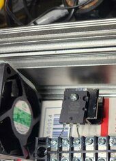
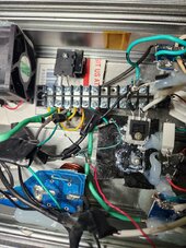
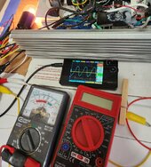
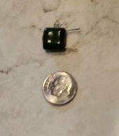
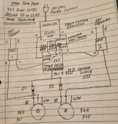
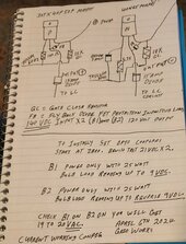
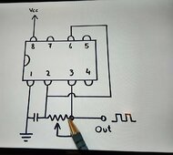
Moved 555 timer to the other end of the inverter, about 6 alligator clip jumpers no longer needed, short direct solder connections to the timer and opto couples/potentiometers.
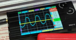
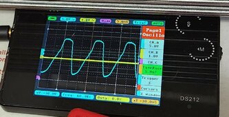
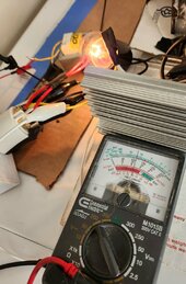
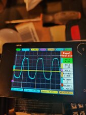
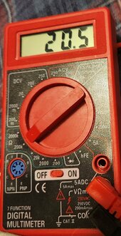
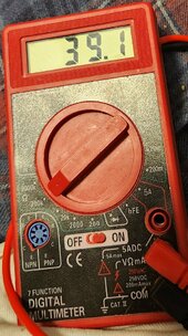
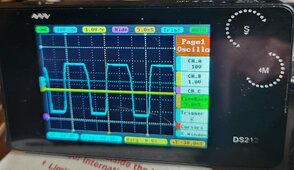
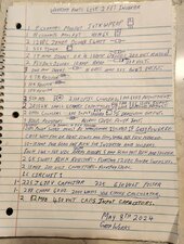
12VDC power supply for 555 timer 60Hz signal works perfect except P channel stopped working after the voltage went from 9 to12VDC , see a small signal but something is missing. Power supply from good used parts, Transformer 120VAC to 11.4VAC, Four 5amp diodes, Filter capacitor, and ceramic load resistor. Nice 12VDC power supply zero cost.
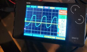
Potentiometer for 60Hz adjustment is working nice, All the new potentiometers perform well.
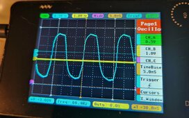
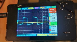
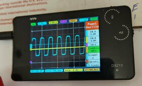
More adjustments needed for the NPN transistor circuit for inverse square wave.
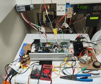
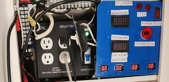
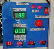
Doing everything I can to make the next dual 180VDC solar test a success, If it doesn't work next step is dual 140VDC solar input and After it works again I will back fill with additional solar panels for more amps.if needed.
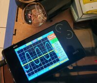
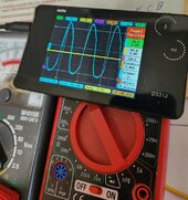
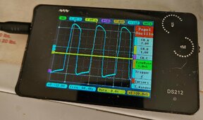
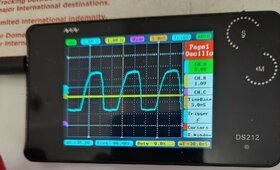
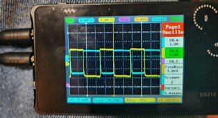
Need another day, several solid steps forward today, Collecting good data on driving the FETs, any spikes on the oscilloscope means you are overdriveing something. Closing in on the exact settings for the optic couplers also FETs big amps of energy in the current wave form can't wait to see it run.
More soon
12VDC power supply for 555 timer 60Hz signal works perfect except P channel stopped working after the voltage went from 9 to12VDC , see a small signal but something is missing. Power supply from good used parts, Transformer 120VAC to 11.4VAC, Four 5amp diodes, Filter capacitor, and ceramic load resistor. Nice 12VDC power supply zero cost.
Potentiometer for 60Hz adjustment is working nice, All the new potentiometers perform well.
More adjustments needed for the NPN transistor circuit for inverse square wave.
Doing everything I can to make the next dual 180VDC solar test a success, If it doesn't work next step is dual 140VDC solar input and After it works again I will back fill with additional solar panels for more amps.if needed.
Need another day, several solid steps forward today, Collecting good data on driving the FETs, any spikes on the oscilloscope means you are overdriveing something. Closing in on the exact settings for the optic couplers also FETs big amps of energy in the current wave form can't wait to see it run.
More soon
Last edited:

 not sure if it will work at 180VDC but already know it runs at dual 140VDC.
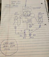

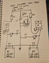

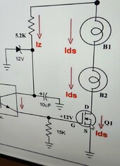

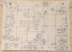
 Caution connect earth ground that appears between B1 and B2 at your own risk, not tested yet and on the surface looks electrically sound and really hope it works But.