GridWorks Green Solar
Solar Innovator
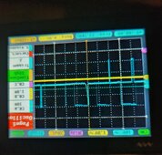
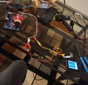
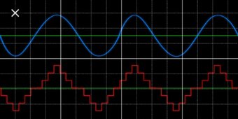
Sorry have been decking the halls and other activities surrounding the holidays, It will be a short time till I am back to working on a live power board. Guess you are interested in the pure sine choke value mH and what it does for the sine wave compared without. Will be glad to test.Nice,
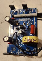
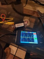
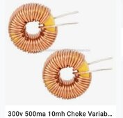
As we know you have oscilloscope can you measure signal before " L " or just after Fet?
Also do you know value of " L ",it should be 3mH?
Best
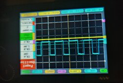
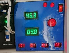
In the meantime trust me it is very important to have the best sine wave power possible before entering the ISO transformer.(you will get a roaring sound from the ISO if the sine wave is off even a little bit.)
The ISO transformer rounds the sine wave even more for really clean AC power, project system runs motors/inverter drive and electronics well.
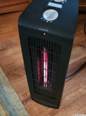
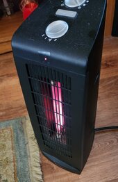
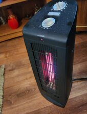
Voltage controlled quartz tube heater is a big hit this year in the living room.
My rat terrier has figured out 5-6 feet away from the heater is a sweet spot.
More soon
Last edited:
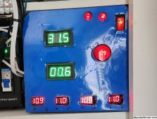
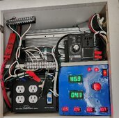
 If the FETs fail on the power board DC power could be directly sent to the connected devices/appliance.
 ️
️
")