diy solar

diy solar

New no battery pure sine wave solar power system with smart switchers.

Ice is gone but removed a section of new guttering from the northern facing side of the home (far right of the picture).

Must do a big repair before starting project system upgrades.

Solar panels at 22 degrees tilt in central US self clear of snow faster and produce more power, visual example of how to get more with less maintenance.

Panels point due south.

More soon
 

Attachments

  • Screenshot_20240125_080923_CloudEdge.jpg
    Screenshot_20240125_080923_CloudEdge.jpg
    279.9 KB · Views: 1
  • Screenshot_20240124_091437_CloudEdge.jpg
    Screenshot_20240124_091437_CloudEdge.jpg
    291.2 KB · Views: 1
Last edited:
NOTICE:

During a recent migration to a new server this forum has converted several different emojies to question marks.

I am sure about the statements made on this forum, hope SYSOP can restore the original text emojies.

Best wishes
 
Declassified Air Force electronics training film, What if the DC capacitor was charged 15 or 30 or 60 times a second by one Mosfet, choke tuned for 60Hz pure sine output
R would be the output transformer.
L is the choke 5-10 mH.
C is a big capacitor.

I have plenty of good spare parts to eventually test this, If successful a new type of pure sine inverter is born. Love the simplicity of the design.

My EV battery is on US soil now.

System updates soon.

Best wishes
 

Attachments

  • 20240129_153353~2.jpg
    20240129_153353~2.jpg
    186.7 KB · Views: 14
Last edited:
Everything continues to work wonderfully, Have collected all the tools and supplies for the upgrades but just not the right time maybe tonight I will get started, Beautiful sunny day and quartz tube heaters continue to amaze.

More soon
 
Due to a no ice in the side by side fridge, turned out to be a dirt covered condenser coil air flow problem.(Fixed) freezer could not get below 26 degrees Fahrenheit,The ice maker needs 10 degrees to zero to operate normally.

Did not get started on the project system upgrades yet, need one more trip to the supply store and expect at least two more sunny days of good conditions.

More soon
 
Trip to supply house was successful, starting upgrades soon.

MIL Convinced putting the output ISO transformer where the scope picture is located and using one of your two FET power board drivers as the signal driver in the photo may work well for power production. Larger capacitors and choke will be required to tune 60Hz power.

Project system is amazing 5 days of blue sky. Best wishes

Reading about a lady getting a 600 electric bill up 146 dollars from last month during this cold winter weather.

Solar panels and heat pumps can reduce the yearly cost to heat and cool a home.
 

Attachments

  • 20240205_205305~2.jpg
    20240205_205305~2.jpg
    208.3 KB · Views: 13
Last edited:
Upgrades scheduled to begin Friday and Saturday, Flawless operation since previous shutdown also for upgrades.

Onto several somethings with the project system, 29 degrees Fahrenheit last night, running full quartz tube heater in the living room today yes another blue sky full power production day.

Voltage controlled relays provides inverter overload protection and automatic load management a real dream come true and much better than what I was doing earlier.

ISO transformer isolation of the power board is key to big power production, You can ground the inverter case but must insulate and isolate the power board from earth ground. This provides a silent background noise for precise FET switching and big power production.

Secondary ISO provides system voltage boost (MPPT effect) for better full sun power production mono crystal solar panels show the best boost in output, also provides 24/7 power for about 500 watts of electronic accessories.

Best wishes, more soon
 
Just getting started system shutdown at dark tonight.

New labels on the display panel to start with, Main thing is not to damage the system works fantastic more than a solid week of full sun conditions.😀

Successful shutdown opened PV main DC switch, turned off secondary ISO transformer and about 3 seconds later turned off the CPU power.

Upgrades in progress, more soon
 

Attachments

  • 20240209_155035~2.jpg
    20240209_155035~2.jpg
    131.4 KB · Views: 9
Last edited:
Upgrades progressing well about 1/3 done so far, planning Tuesday to restart project system.

Upgrades include fuse power boards #3 and #4 at 10Amps max, put voltage controlled relays 2 and 3 in charge of controlling the output of #3 and #4 power boards also ready the wiring on voltage controlled relay 4 for use.

Have removed all wire nuts on high voltage wires except one big blue wire nut on the main DC feed. Using terminal strips for the upgrade.

Rework on several ugly connections on the first terminal strip and adding one more for the secondary ISO transformer output. Nice for testing DC power and capacitor discharge if needed.

More wire ties and so on.

All 4 voltage controlled relays wired, programed and ready to run, display panel fits better in it's space due to improved wire routing.

Back soon
 
Last edited:
Project system is up and running again, 8:30 AM needs more wire ties and a final tidy up on the exposed wires.

Large Combo unit has two fiber optic cables showing CPU status for power boards #3 and #4.

So far so good, not expecting much solar today rainy overcast sky.

More soon 😀
 
It is working again all 4 power boards active need full sun for final testing.

Note the two fiber optic CPU status lights off power boards #3 and #4, used 1 inch of #10 wire plastic jacket to make a solid connection to the CPU red led.

It is solid and fully fused, expect years of good service from this system, output ISO transformer sits behind the clothes dryer.

Small system that fully delivers even on a really crappy solar day.

First look picture.

Voltage controlled relays just switched over to full solar at 10:30 AM everything is working as planned, Awesome.

All the power board outputs have passed initial loading test, I am amazed with the the performance on this heavy overcast sky day.

Upgrades in the past two cycles:

Metal display, New labels, Metal duct for ventilator.
Remove almost all wire nuts and replace with terminal strips, Did not use crimp connectors at the terminal strips on purpose have had nothing but trouble with crimp connectors in power production, although some of the connections look ugly all have been pull tested and passed. Terminal strips work!

Voltage controlled relay output for #3 and #4 power boards easy access wiring to use relay 4.

Transfered one voltage controlled relay to the main display and added three more, the first three are active and the 4th will soon have a job to do.

Improve wire routing and added additional safety fuses to the system.

Not that hard to build when know what to do, Have been working this about 6 years and pleased with the results.

Best wishes
 

Attachments

  • 20240212_101302~2.jpg
    20240212_101302~2.jpg
    261.6 KB · Views: 2
Last edited:
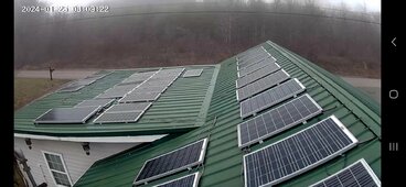
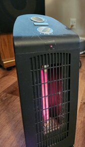
Sun is shining and the heat is running full power in the living room on a really cold day.

System runs great, full automatic but I do turn the heater to Hi when I notice full sun conditions.

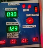
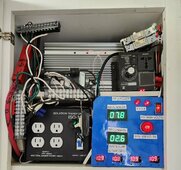
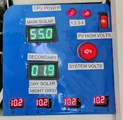
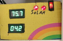
Last picture full power test Max 15Amp what is on the blue display now is just normal loads of the day Hi heater, lights, house fans, security cameras, 2 monitors, 2 stick computers and a mini fridge running right now.

No batteries, Low cost, low maintenance, gold standard solar power trust me you need one.

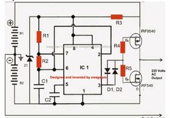
Ran this thing for years with no displays just use a clamp on amp meter to check operation, Simple power board inverter with case, 2 ISO transformers, doorbell transformer, diode bridge and fuses make the system and it can serve you well. Just add 180VDC solar array of your choice to make magic.

Running 120VAC mini split in the summer off the system, successfully cooling the four largest rooms of the home, surprising moisture removal and comfort.

Minimum 9 standard 12VDC panels for 5amps output

18 panels get you 10 amps.

27 panels gets you the project system maximum of 15Amps.

Get as close as you can to 180VDC full sun exposure no load voltage test. Be careful during this test three or more panels in full sun can kill you ⚠️
9 standard 12 VDC solar panels in series will get you about 181 VDC.

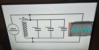
Natural super efficient power blender keeps the bucks in your pocket while boosting full sun solar production with voltage boost MPPT effect (something you can see on the quartz tube heaters).

Just add a system voltage controlled relay to drop the extra loads to off or with a switcher device transfer to grid for 24 hour operation, if the setpoint is put at 98VAC for the lower limit you will protect the green power inverter from overloads and have automatic load management of the extra devices all with one voltage controlled relay. First one on the left of the display commands the whole house green or grid and keeps the inverter happy. Makes a simple decision 115VAC On and 98VAC Off.

Extremely fast response has saved several power boards.


Best wishes all
 

Attachments

  • 20240213_115845~2.jpg
    20240213_115845~2.jpg
    120.7 KB · Views: 8
  • 20240213_115752~2.jpg
    20240213_115752~2.jpg
    207 KB · Views: 6
  • 20230218_111320~2.jpg
    20230218_111320~2.jpg
    289.5 KB · Views: 3
Last edited:
Except for phone automation the Project system is complete, my attention will turn to making a pure sine inverter with one or two MOSFETs if possible.

I have been inspired by a forum member to give it a try, also found out the correct LC circuit can correct modified sine or square wave to proper pure sine.
Switching between two inverted solar arrays and LC sine correction should equal big pure sine power production 💚

Going to build a low voltage example and just like the project system Going to up the voltage when I get pure sine.

Ask questions if you need assistance with anything.

Best wishes
 
Last edited:
Suggest you download all diagrams on page 22 and beyond, and read all the way up to page 37 for the best tips and tricks.

Pay close attention to anything regarding voltage controlled relays, have used them in the past for 12 volt battery charging but in the role of inverter protection and downstream load management it is a real dream come true, Voltage controlled relays and grid/battery backed secondary ISO make for 24/7 about 550watts electronics off the system. Has a stabilizing effect that enhances what solar can do on it's own, This hybrid power system can do more than you would normally expect and can be customized to do much more.

Not complex just do each step well good soldering connections is a must, needs in and out glass fuses, provide spacing and use the gray ISO pads included in the kit must have electrical and mechanical isolation from earth ground or the power board will not servive. I highly recommend the system and do not regret anything to get to this point.

Best wishes
 
Last edited:
Parts ordered for two MOSFET flip flop inverter (10) IRF9540 FETs and (10) IRF540 FETs (10) NE555 timer IC packages.

Lots of extra parts ordered and I will make a PCB after I find the best possible way to make pure sine power with just two MOSFETs using two inverted solar arrays for direct drive 120VAC and LC circuit for perfect sine wave off an ISO transformer.

Using what I already know about this subject you can expect fast progress on the 2 FET inverter, May need an EGS002 or DY002-2 CPU if the NE555 timer chip is not stable enough.

Hope to make several and sync them for 2X 4X and so on power output 💚

More later, best wishes
 
Last edited:
Found a nasty start problem with the flip flop inverter, Diagram clearly shows 220VAC output but the main FETs only have a 100 volt max rating on the drain per the spec information.

Still going to proceed as > 98 volts pure sine will run most electronic devices and can upgrade the FETs for more volts/amps after I get pure sine working correctly.

Best wishes, more later
 
Need help with selecting the proper set of MOSFETs or Transistors for the push-pull/flip-flop inverter, need 200 volts 15 Amp switching of DC, need fast switching for 60Hz power.

IRF9540 and IRF540 19Amp and 100 volts maximum, The IRF9540N and IRF540N have 33amps and the same 100 volts maximum limit.

One data sheet says easy to parallel but doesn't provide any information on how this might be done, also doubt it changes the 100 volts maximum limit.

The above mentioned parts received a ding for constant drain current when operating at near maximum voltage in other words the parts run hot even when not doing much work (I certainly hope to do better) baby steps till I get it working full sine.

Please help, switching between a forward DC solar array and reverse DC solar array to make 60Hz AC power.
 
Last edited:
Starting to find P channel and N channel MOSFETs in the 200 volt range.

Looking for a matching pair, Could still use help in the search IRF640N is a 18amp 200volt N channel, Looking for a matching pair of N and P channel components.

IXTK90P20P is a similar P channel 200 volt Mosfet but not matching.

Surprised to find 900 volt FETs available.

More soon, expected ordered parts to arrive Monday, still have a EGS002 new in the bag for possible as a driver CPU, lots of new and used parts for testing.

Found something sold as a matching pair IRFP9240 P channel and IRFP240 N channel. Although the P is only rated at 12 Amps and the N channel is 20amp both 200 volt ?
 

Attachments

  • Screenshot_20240222_215922_Firefox.jpg
    Screenshot_20240222_215922_Firefox.jpg
    46 KB · Views: 1
Last edited:
Never stop to improve,but only way,Best
Looking for the simplest best way to make pure sine power with two main Mosfets and then I am going to make high quality kits with printed circuit boards and free information so you can make your own.

12amps is enough for a start system but planing to X2 X4 on amp output. Still looking for the correct set of MOSFETs.

Must have 15Amps for level 1 inverter output.

More soon, best wishes
 
Last edited:
Found a set of MOSFETs that might just work not matching but exceeds all requirements needed.

IRFP460 BF N- channel 500 volt 20amp MOSFET
IXTK40P50P P- channel 500volt 40amp

Makes me happy to find parts that can exceed 15 amps and 180 volts 60Hz.

Best wishes
 

Attachments

  • Screenshot_20240223_145207_Firefox~2.jpg
    Screenshot_20240223_145207_Firefox~2.jpg
    21.6 KB · Views: 3
  • Screenshot_20240223_144003_Firefox~2.jpg
    Screenshot_20240223_144003_Firefox~2.jpg
    18.5 KB · Views: 3
Last edited:
Basically the two photos show what I am going to attempt with different parts, the left diagram will get bigger much better FETs and storage capacitors for high voltage DC input from the solar panels to better handle a surge, the photo on the right will be the same output LC filter circuit as the the one found on the project power board.

Interested in the earth ground between B1 & B2 if the project system was grounded in that manner the board would fail.

Interested in the pure sine wave we are going to get.

Bet one configuration or the other is going to provide big efficient direct drive power production with the inverted solar PV arrays, curious about what solar PV DC input voltage will result in 120VAC output. Output ISO transformer will be located where the oscilloscope is located.

Going to reconfigure a bad project power board for the LC output circuit, FET mounting and input DC capacitors, the 555 timer IC will be glued to a second board and configured for 60Hz signal. Once I get it right going to make a printed circuit board that makes it easy to build and mount in a standard inverter case.

Excited to see it work might have to design a soft start to prevent surge problems.

Best wishes
 

Attachments

  • Screenshot_20231109_133354_Firefox~3.jpg
    Screenshot_20231109_133354_Firefox~3.jpg
    78.5 KB · Views: 3
  • 20240205_205305~2.jpg
    20240205_205305~2.jpg
    208.3 KB · Views: 4
Last edited:
I have this,just do`nt know that to do :)
-https://www.next.gr/oscillators/Multiple-waveform-generator-circuit-diagram-l59906.html
Multiple-waveform-generator-circuit-diagram.png
-https://www.instructables.com/Grid-Tie-Inverter-V4-1/
General_Schematic2.png
-https://makingcircuits.com/blog/h-bridge-inverter-circuit-using-ic/
DC for all
UPS220.jpg
 
Why not 40N65?
I see another mix also.Best
See no reason why the 40N65 would cause any problems in the role of the N channel MOSFET in the new inverter, note the 40N65 requires three support components not shown on the left diagram, going to build on the original design then expand quickly (Going to build two expect one to fail quickly)

More soon
 

diy solar

diy solar
Back
Top