GridWorks Green Solar
Solar Innovator
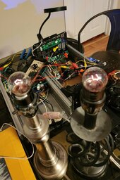
Almost home run have simulated P channel also driving the N channel on a second two FET board,
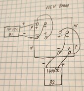
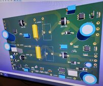
How to make this work the 555 timer main pin 3 square wave output goes directly to two diodes in opposing directions next each diode feeds a set of 50K to 100K potentiometers (resistors) next 800 ohm resistors on the four outputs going to the optic coupler LED inputs
It is important to have four individual indepent controls because of different output levels from cross driving the FETs P & N channels, once you get it correct you can test and go with fixed resistors also remember to readjust the cycle frequency to 60Hz.
Need soldering on potentiometers and more benchwork, looks like a win coming for 100% solar panels usage with dual two FETinverters.
More soon
 ️
️