diy solar

diy solar

New no battery pure sine wave solar power system with smart switchers.

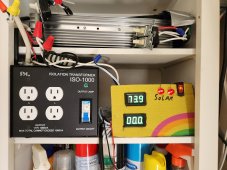
Ugly vent intake works, back to 24/7 running the mini split on seamless secondary power if desired.

Lots of options for the future, Best shot at making it look pretty and less ducting is swap the inverter down one shelf and putting the display and secondary ISO on the top shelf, ventilator with small amount of duct work stays on the very top of the cabinet. Would like to be able close the cabinet door completely when finished.?

Sorry still working out the details but if it helps you get it right the first time it is all worth the effort, Love the project system will not stop till multiple working examples exist, will go to the extreme to help you see the power?

**(One free new FETs 40N65 power board and case fully functional Inverter unit hand delivered to one lucky person that will assist in me testing the project system.)
**(PM me to claim the pure sine inverter and assistance, open offer till I say otherwise, will work with you on the timing and location to get a working example.) (Contenitial US only)
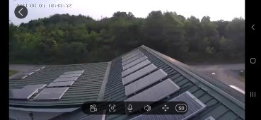
**(To have working need 9-16-27 project array PV array panels working 180VDC! and a 15-16 amp main ISO for safety add one more solar panel if off grid. Needs to be car accessible please)
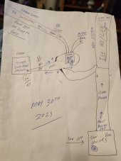
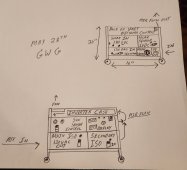
First picture:
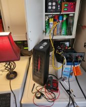
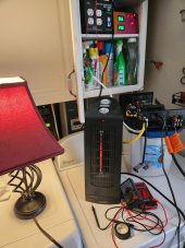
The more I think about the rolling cart version of the power system the better I like it, 20 inches tall, 16 inches accoss and 12 inches deep should work nicely.


Like a gas generator but no gas and nearly silent operation, add one of the newest Li-Ion battery units for the home run, I am telling you people need this power unit, money to be made from building exactly what is shown here.

Look again

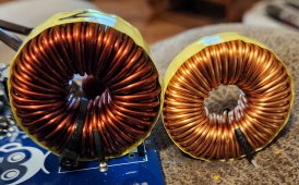
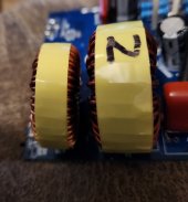
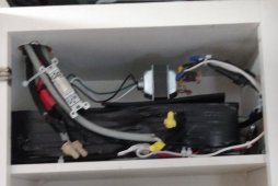
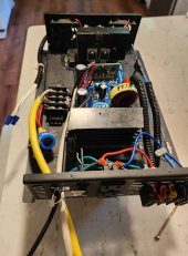
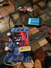
**Just finished upgrading a new factory board with the hard to kill New 40N65 MOSFETs, New 2000-3000 watt pure sine choke. Bench tested nice pure sine wave power 60Hz Just needs installed in a metal case.

**Fully adjusted for max power meets all project requirements.
Your prize power board is ready ??♥️

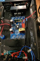
**Prize board is now mounted between two serious heat sinks in a metal inverter case with fans, fully isolated needs the silicone to set for one day before soldering on the wires and loading it up on a bench test. Not the prettiest of cases but already has the mods needed for the power board.

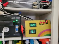
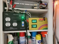
**Willing to wait for you to be ready as long as you are serious about the array and 15Amp ISO,About $850 for 9 standard solar PV panels and $400 to $500 for a 15Amp ISO transformer.

**My medical grade 16Amp transformer was purchased used on Ebay for $200 (They never go bad) used or mixed panels work fine target DC voltage is 180 ! voltage in full sun, be careful.

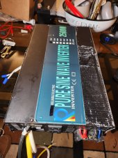
Previous factory board from that case still running after 4 years of service in line for the 40N65 MOSFET upgrade and main backup board for the main project system.
 

Attachments

  • 20230528_212031~2.jpg
    20230528_212031~2.jpg
    151.3 KB · Views: 4
  • 20230529_130713.jpg
    20230529_130713.jpg
    161.2 KB · Views: 4
  • 20230529_161300~2.jpg
    20230529_161300~2.jpg
    165.1 KB · Views: 4
Last edited:
Offer is for real in the previous post, live full load testing likely tomorrow on the project full bells and whistles inverter board, power board and case.

About a $200 inverter value for free, having me help you priceless ?

Best of luck
 
Last edited:
Approximately 24 hours later on the offer and not a single question, please ask if you have concerns.

My plan is to swap email addresses and assist you in having a dream PV power system, Awesome power system that is likely to last five or more years into the future.

Just use the power board system and tell others what you think about it.

Yeah you can spend alot more money and not get anything close to what I am offering.

You handle the majority of the DIY and I will make sure It works and it is safe.

Unique and expandable power unit is yours, email me any time during my retirement for guidance on anything.
If for some reason it doesn't go as planned the solar panels can be used to drive another off the shelf solar system.
Win win situation.

Best wishes
 
Last edited:
Nice solar day, new sun sensor is in control of it all, Final tweaks done for now.

Getting ready to go to Michigan for a few days be back soon.

Rolling clouds sun sensor controlled switchers units do something I like, during the scramble for energy with sun input failing because of clouds the units perform a quick drop of the big appliance and start a timed delay that will do a easy restart to either grid/secondary or return to solar if the sun sensor says so.

Quick drop of larger loads and staggered return to normal, Mini split performs perfect with 45 seconds delay it's computer provide additional delays to return to normal. 80% sun 20% clouds today. Squeezing out every drop of sun still manages 25% discount on cloudy conditions as long as it is not raining or snowing.

Best to all

Prize system passing full load and voltage bench testing, needs two blocking diodes to be a complete project inverter. ?

Perfect test day and perfect results.

Grid backed systems never stop operating with nessary restart delays,PV new/old systems and deep cycle battery on the older system run everything else.

Bottom line it works, lighting runs stable from the new power system 24/7 especially with deep cycle battery supported secondary power from a much older system. Mini-split is running perfectly and will be on grid power way before 7PM today.

Mini-split heat pump is the only thing active in the house back to back 24/7 days of cooling, house is a crisp comfortable 71.8 degrees Fahrenheit, really nice.

I have solved a technical puzzle with off the shelf parts, unique power board recipe for running the most demanding electronics mostly PV powered during the day with just enough seamless secondary support to keep it voltage boosted and efficient over a wide range of operating conditions even after hours.
 

Attachments

  • 20230530_141212.jpg
    20230530_141212.jpg
    76.3 KB · Views: 3
Last edited:
I need help! Not connecting with the target audience, If I am reading things correctly no one in seven months has connected 9 series or 16 or 27 panels to a power board and tested the operation.

I have seen a few glowing responses from some that get what what has been accomplished here, Offering you a chance to have one. You really need this power unit, most people could find a real world use for it I am sure.

Like my Decker Rat Terrier, a blend of all best dogs this guy cannot help but be a great dog, same with the project power board system six years of stuffing the best ideas in one spot you can expect to like how it works.

Best to all

Clouds rolled in early around 4PM ending the solar Day, new power system never failed to please, also did two loads of front loader washing on a less than perfect solar day ?
 
Last edited:
Information to help you size and identify what power board you may have purchased, smaller choke is for the 1,000 watt board, large choke is the 2,000 to 3,000 watt version.

4 of the 20N60 FETs equal 1,000 watts.
8 of the 20N60 FETs equal 2,000 watts.
4 of the 40N60 FETs equal 2,000 watts.
8 of the 40N60 FETs equal 4,000 watts.
Project recommendation:
4 of the 40N65 FETs equal 2,000 watts.
8 of the 40N65 FETs equal 4,000 watts.

Each FET requires it's own diode and two resistors to operate, adding a small load to the 12VDC power board bench testing allows for heating of operational FETs to verify operation with a finger touch, Looking for symetrical correct sine wave 60Hz US on an oscilloscope.

Caution ⚠️ standard board is only rated for 3,000 watts need power traces beefed up to go beyond 3,000 watts.

Caution ⚠️ always recommended safe shutdown procedure (Turn off PV power,Turn off secondary ISO power and two seconds later turn off the power board CPU.)
Due to a higher risk of 8FETs getting out sync during the shutdown processes Safe power down is a must especially in full sun conditions.

New 40N65 FETs add a whole new level of durability,voltage and current.
Maximum 8 FETs per CPU recommended CPU voltage needs to be 16-18 volts for 8FETs and 12-16 volts for the 4 FETs versions, board has diodes so AC or DC is OK, have always liked how a 16VAC doorbell transformer runs the CPU with one switch.

Twice ordered 1,000 watt boards and was sent 2,000 watt boards.?
Board comes factory assembled or in kit form, kits can be combined for 8 FETs version or handy for repair.

Last kit came with the better 40N65 FETs, I have since bulk ordered more.?

Best wishes
 

Attachments

  • 20230530_201046~2.jpg
    20230530_201046~2.jpg
    428.4 KB · Views: 4
  • 20230530_201117~2.jpg
    20230530_201117~2.jpg
    161.5 KB · Views: 3
Last edited:
Would like to discuss the following PV and grid amp draw photos Day/Night operation.

First how to read the digital amp meters, first digital meters are full 100 amp DC current sensors are wound ten turns each for detailed 10 amp range, maximum on each display is 9.99 amps displayed 99.9

My typical photo shows a large number for solar PV and a smaller number for secondary power usage in many cases secondary starting with a zero to indicate less than one amp of secondary power usage.

Highest PV amp draw to date is the 82.3 display photo actual amps 8.23 from solar.
Calling your attention to the last two photos same exact load one day time and the other at night photo.

Although the PV is rated for a absolute maximum 10 Amps @ 18 panels and the secondary ISO is fused at 10Amps during a day time full sun the system can be configured to actually provide 8.28 + 7.39 = 15.67 Amps maximum project system fused at 15amps.

If you just consider the last two photos that is 7.39 plus 7.39 equals 14.78 Amps basically 15amp maximum once again.

This is why I say you can operate two 120VAC mini-split air conditioners off 18 panels in full sun. Current project system night time configuration is 831 watts to keep the mini split alive 24/7 but have seen it do so much more in testing.

Secondary ISO factory 115 volts DC 550 watts seamless secondary, 23 added secondary turns 136volts 830 watts secondary, 63 turns 160VDC 1,200 watts of seamless secondary. ⚠️ need 15amp Secondary ISO transformer and system high AC voltage warning for going past 23 added turns, low loads can see voltage passing 125VAC.

Have lost the desire for max load testing, sure I could provide higher numbers but already pushing the maximum 15 system amps now.

Rolling clouds yesterday and the system never faulted on support of the loads, House stayed cool and the lights burned steady with full PV sun the secondary draw is less than one amp ?
Awesome ?

Just looking at the first picture 8.28 PV amps + 1.51amps secondary equals 9.79 amps on a 10 amp max system configuration, Most will never understand till you see it in real life what a big deal this power system has to offer you, about to add the final 9 solar panels for the Big win, You need this power board system, start small 9 panels and $55 power board and expand as needed.

Best wishes
 

Attachments

  • 20230305_111026(2).jpg
    20230305_111026(2).jpg
    243 KB · Views: 8
  • 20230315_195901(2).jpg
    20230315_195901(2).jpg
    246 KB · Views: 8
  • 20230316_103956(1).jpg
    20230316_103956(1).jpg
    258.3 KB · Views: 8
Last edited:
Working two days in a row in rolling clouds conditions, looks simple but a real pain to figure out, mega cheat sheet, combined every old and new system under the version 5 sun sensor.
12VDC from deep cycle batteries in older solar system, 12VDC power adapter can run relays ( CPU requirement doorbell transformer or ISO protected power supply or stand alone 12VDC solar panel only)

Ran across a lab article suggesting that static charges in electronics can be suppressed with positive or negative ions, Most are familiar with smoke eaters and air cleaners that use ion technology. Small chances to ditch the ISO transformers in the power board system. Forced air cooling that carries the correct ion charge could be the second answer to the big bias issues.

More later
 

Attachments

  • 20230531_143912~2.jpg
    20230531_143912~2.jpg
    95.1 KB · Views: 7
Last edited:
Have heard back from a friend that suggested they are too busy with life/family and other to work on the power board system.

I understand that perfectly, and have some advice for others, take a complex task and break it down into smaller pieces for instance if you are building a solar array install two panels per weekend or day off in a month or three you will have the core power production done, most of the things in this thread were built at the kitchen table over weeks and months low voltage tested and set aside till ready to use.

The results is you will save big and eventually end up with exactly what you want built exactly to your standards.

I will help you along the way with advice and maybe visit your location for more specific details if you want.

Unique power system runs daily unassisted and definitely out performs the rest, got an unheard of 11 hours PV solar on the side by side fridge, solar day ended at 8PM started 9AM.
New sun sensor and 180 volt series PV arrays on a directly driven power board at work.?

Still available to who ever will claim it, Crown Jewel project 40N65 FETs inverter carefully built and pre tested 2,000 watt unit.
Just need 180VDC! of PV solar panel power to see the magic. 12-16VDC or AC to run the CPU (Single 12VDC solar panel or Doorbell transformer 16VAC or other Isolated power supply to run the CPU)

Part of the problem is big steps forward in the past few weeks and nobody is looking anymore. Getting more day time PV power and amazing performance from a 120VAC mini split heat pump off the project system.

Best wishes to all
 

Attachments

  • 20230529_161300~2.jpg
    20230529_161300~2.jpg
    165.1 KB · Views: 3
Last edited:
Prize 2,000 watt 180 VDC inverter is all new factory board and upgraded 40N65 FETs with over sized heat sinks. (Fully adjusted and bench tested)

The case is an ugly old inverter case with 12VDC fans wired for half speed series operation and factory plug outlets and terminal strip for directly driven output to the main output ISO.

(All tested good) (case shown in previous photos)

About a $200 inverter value and comes with expert tech support. Yours free just claim it. (One and only prize inverter for one lucky person)?

All wires will be labeled and capped, with an instruction sheet as a quick start guide, free shipping to Contenitial US or possibly hand delivered if agreed upon by both parties in advance.

Best to all

Old picture of the prize inverter running at 800watts, new power board is rated for 2,000 watts a perfect match for 18 standard solar panels.?
 

Attachments

  • IMG_20220908_125529967~2.jpg
    IMG_20220908_125529967~2.jpg
    166.5 KB · Views: 3
Last edited:
Heading back home early morning from Michigan to east Tennessee.

Left the 120VAC mini split on the new power board system and all remote indicators say it is still running smooth daily. Not worried everything is glass fused and automated.

Main plan after getting home is to order 9 more mono silicone standard 12VDC solar panels with Z mounting clips on the metal roof and add to the existing 18 panel array, already running two of the 2,000 watt boards with the ultra stable four 40N65 FETs configuration, distribution of the new power will be easy.

Panels will go up one at a time over several days, the slim mono crystal panels are easy to install with a small dab of 100% RTV silicone on each screw.

I will report on the progress, system fuses will need to be increased from 10 to 15Amps and 10amp current sensors will need recalibration for the increased power availability.

More soon

Back home everything is working perfectly, Recommend the system!, Have no clue why no one has claimed the prize.

Best wishes
 
Last edited:
Order complete on nine 12VDC mono crystal slim 100watt solar panels, also 4 (Z) clips per panel, Expected delivery Jun 17th total cost $1,026.00

Not a chance in the world I would have ordered these PV panels if I had any doubts about the new system paying me back many times over.

KIA has contacted me about a recall on the 2016 Soul EV mentioned in the letter replacement of the high voltage battery, I could not be happier to take the car in for service this time.

More soon
Awesome on the new panels
 
Awesome on the new panels
On the lower level is six of the slim mono crystal panels, the plan is a row of nine just to right of the six, Looking forward to using the extra watts on the new system.

I don't mind waiting till you are ready to set up a working power board, think you mentioned emergency service usage, I am betting if you see it working your plans will expand.

If you claim the prize unit I will work with you and your schedule to have another functional example, like I said once you see it run bet you figure a daily use for this strong performing pure sine inverter.

Best to all
 

Attachments

  • Screenshot_20230605_184354_CloudEdge.jpg
    Screenshot_20230605_184354_CloudEdge.jpg
    561.7 KB · Views: 5
I would definitely like to claim it. What do I need to do?
You just did 1686007445732.png PM me when ready, we will work out the details later email, address etc.

Still need a terminal strip and the blocking diodes to be completed and one final bench test of the Deluxe Inverter.
Congratulations!

I will PM you the moment the screws go in the cover and gets my final approval.
 
Last edited:
Final additions to prize inverter, Here is the full safety blocking diodes rated for 20amps system max amps is 15Amps.

Diodes are in the diagram are for back flow safety keeps secondary ISO power and charged capacitors from reverse feeding the PV panels (PV panels contain a similar set of Diodes that do the same exact thing) my main concern was the wiring between the panels and the Inverter and you working on them.

Although the diodes block backfeed they also pervent forward flow until they can overcome the ISO secondary voltage, this causes a system wide voltage boost, solar panels in full sun produce more real power at higher voltage the MPPT effect.

Early indications 10 to 20 precent additional power depending on type,construction,age of the solar panels.
Early testing new mono silicone panels are most excited by the boost effect. ?

About one more day to call it done on the Deluxe Project Inverter.

Prize Inverter will be very strong.?

Note: + & - signs are reversed in the first picture, PV positive power always connects to the unbranded side of the diode.
 

Attachments

  • 20230606_150558~2.jpg
    20230606_150558~2.jpg
    162.2 KB · Views: 4
  • 20230606_160052~2.jpg
    20230606_160052~2.jpg
    146.6 KB · Views: 4
Last edited:
Have run into an issue with the banded direction of the PV blocking diodes, until I have a chance to get to the bottom of the error, Keep in mind solar panel positive (+) goes to the non banded side of the diode. One or more diagram drawings may contain this error, won't cause damage but it will not allow PV power to reach the power board.

Checked latest diagram on page 22 documents post the blocking diodes are 100% correct ?

More soon
 
Last edited:
Prize Inverter has passed all bench testing and full load test.

Just needs cover put on and instructions sheet to be shipped out.

This unit works great ?

Yellow PV input to powerboard, White is secondary ISO transformer to power board.

Cover is on ready to ship unit.

More soon
 

Attachments

  • 20230607_102611~2.jpg
    20230607_102611~2.jpg
    172.7 KB · Views: 7
  • 20230607_103017.jpg
    20230607_103017.jpg
    153.9 KB · Views: 7
  • 20230607_120947.jpg
    20230607_120947.jpg
    175 KB · Views: 6
Last edited:
Greetings from Europe and a big thank for contributing from electrician with low knowledge of electronics.We have a similar thinking, and I just plan my 5 kW PV system, with a perspective extension and I would split it on:

Winter
The plan is to use about 200 VDC from PV, with NTC and SSR, through a another socket on the wall.As I concluded with the help of the forums the most important thing is that R from PV and R from the heater be almost identical.Planted comand contactors to switch additional heater, when temperature is reached The first shifts to the second place, the same through the NTC-SSR wouldn't turn DC into AC because of a resistant heater can work directly.

Summer
I like this system for this and the need for AC unit(s).Since you are very familiar with the topic if there is an board inverter with an entrance of about 200 VDCand output of 210-230Acv or some (simple as my knowledge) modification of some existing plates.
With me the grid is 230/400 Vac.

Q- How does Inverter know than it takes 150 V from the PV and the rest of 30 V from the grid?

Sorry on my English.
Seems you found a way to do heaters directly from DC power very efficient, my system is geared to produce standard US 120VAC 60Hz pure sine 15Amp power.
With small changes the system can support 220-240 VAC 50Hz power.


The natural voltage controlled power blender in the project system gives priority to 180VDC PV solar power when compared to the 115VDC to 136VDC of the secondary ISO transformer.

System in the most efficient way possible squeezes out every drop of sun shine savings for you, seamless secondary support allows for a stable platform to run demanding electronics.

Although not project recommended the power board was factory designed to handle 380VDC! input and 240VAC output, jumper selection 50/60Hz.

More soon
 
Thanks,how to change to 50 hz and set to 220V on inverter board,any link?
If I use just for PV and just for AC unit do I need ISO transformer?
This board have undervoltage protection for output?
 
Thanks,how to change to 50 hz and set to 220V on inverter board,any link?
If I use just for PV and just for AC unit do I need ISO transformer?
This board have undervoltage protection for output?
Jp1 and Jp5 on the DY002-2 CPU drive board
Same for EGS002 CPU drive board.
Factory set 50Hz

Boards and CPUs from China I have language issues but CPU can be programmed to do all sorts of things even additional display units.

Input voltage determines output, 360 VDC input gets 220 VAC output. 180VDC input gets you perfect 122VAC output.

Avoid anything with a earth ground,(power board damage)ISO fixes power for normal neutral and ground. Things like car charging and mini splits need to see a earth ground to work.
 
Last edited:

diy solar

diy solar
Back
Top