diy solar

diy solar

New no battery pure sine wave solar power system with smart switchers.

Project system running smoothly, zero grid usage when sun is shining.

Running heat in living room and back hallway, also running the normal stuff 24/7.?

Natural Power blender is amazing/efficient, makes me smile every time I see this.?

What this display really means is I am handling the loads with 100% solar power and have extra capacity to handle even more.?
System Voltage is 108VAC and everything runs steady till 98VAC or below is detected and excessive loads are shed to off/secondary/grid.

Trust me you need one or more of these things.

Best wishes
 

Attachments

  • 20231111_105701~2.jpg
    20231111_105701~2.jpg
    1 MB · Views: 2
Last edited:
Looking forward to testing Voltage controlled load management on EV car charging, never tested before but should add a needed layer of protection for the inverter and automate the whole process.

Going to control the output of the three inverter power boards on/off and monitor the system voltage of each.

First attempt at computer control of the project system,

More soon
 
It has begun solid metal display, getting rid of all wire nuts is next have terminal strips for everything.

One more CPU indicator needed for the triple board 6,000 watt combo unit and voltage controlled relays.

Fist picture night operation, second picture heavy overcast day.

More soon
 

Attachments

  • 20231113_185342~2.jpg
    20231113_185342~2.jpg
    847.2 KB · Views: 5
  • 20231114_140943~2.jpg
    20231114_140943~2.jpg
    1.2 MB · Views: 2
Last edited:
If we're ever 25 years deep into a post-apocalyptic scenario where all of the batteries in the world have died and society hasn't recovered enough to produce any more... I want this guy on my team.

In all seriousness, I read through this thread over the past two days, and while I don't have the electrical engineering knowledge to understand all of it, it's clearly a pretty interesting setup. I guess you never did find a way to get rid of that expensive isolation transformer though. Those things seem expensive from when I was looking around.
It helps to think of the transformers as replacement for the expensive batteries found in other systems and the transformers never go bad like the batteries do.
Much less maintenance and cost going through time.

If you can get a deal on used ISOs it is not so bad,they never go bad, also Amazon sells 10 amp ISOs for $200 new, two in parallel will more than cover 15 amp max usege. Project system is 16amps output and 10amp input, can be replicated with three of the New $200 transformers.

Best wishes, Highly recommend the system.
 
Last edited:
  • Like
Reactions: Mil
First attempt at labels on the new display, likely a row of voltage controlled relays accross the bottom soon.

Loads of improvements coming soon.

Metal duct work for ventilator fan and lots more in the works.

Voltage controlled solar living room heater continues to amaze, Quartz tube heater radiation on your face and skin makes winter a bit more pleasant.

Top meter 20amp full scale (75.0 is 15Amp max power, bottom meter is 10 amp full scale, preceeding zero on bottom display is less than 1 amp useage, decimal place needs shifted one place to the left on both displays.

Best wishes
 

Attachments

  • 20231115_221817~2.jpg
    20231115_221817~2.jpg
    757.9 KB · Views: 5
  • 20231116_101722~2.jpg
    20231116_101722~2.jpg
    998.5 KB · Views: 4
Last edited:
"Dymo" labels that are actually stuck on :)

I use plain paper, laser or inkjet printed and stuck on with a glue-stick :)

More permanent labels get laminated before being stuck on.
I promise to do a better job next time, the display is going to increase in complexity with four voltage controlled relays across the bottom and a additional CPU status above, thinking about fiber optic from the LED display on the 3 CPUs themselves.

Quick way to tell you what is going on with the display.

As to not mess up anything I currently have working the current system just moves up a shelf and the voltage controlled relay moves over to the first slot at the bottom of the new metal display the next three voltage relays will control the new combo units three power boards.


By mid January no cardboard duct work for the vent/cooling fan, zero wire nuts in the next few days, may move slim silver inverter on the very top shelf and the combo unit to the main spot, that's 5 power boards 10,000 watts capable worth of green inverters with control and voltage sensor for each one.

More later
 

Attachments

  • 20231117_104943~2.jpg
    20231117_104943~2.jpg
    1.1 MB · Views: 2
Last edited:
Terminal strips have arrived but time is running out to do much more right now, see you after the holiday.

Big changes ahead vent fan with metal duct work, fan will be relocated underneath cabinet and blow upwards, slim inverter will be moved to the top shelf cabinet position, and the combo unit will occupie the prime second shelf space.

Fiber optic 5 CPU feeds LED status indicators for the power boards, Voltage controlled relays for each output, four active voltage controlled relays accross the bottom display soon.

15Amps 180VDC can be channeled through any of the power boards and monitored for volts. Later on expand inputs for more Amps output.

It is my plan to do away with the 4 large flooded batteries in the old system when they expire, easy to move the solar panels to the new Inverters and continue forward, maybe something new to back up the secondary ISO in the future.

Hybrid grid power secondary support works just fine 98 percent of the time to replace batteries in a PV solar power system, really depends on the power company and your needs, a gas generator or Li-Ion packaged backup unit can bridge a grid power down situation.

Love the day after day savings to Heat/Cool/Light/Fans and more on solar power.

Best wishes
 
Last edited:
My EV car is getting a new battery only because it was identified as having a known issue with the high voltage battery in the form of a interim recall notice.

This will work well as I have a good idea about what the next 6 to 7 years might look like. Car factory new 91 miles range for the first five years you can expect 80 miles reliably.

Now I have to go to the dealership and order new eco badges for the exterior as the old ones have started to crack.

Core system has run non stop perfect for months voltage controlled load management is a blessing?

Best wishes
 
Starting voltage controlled relays 4 in a row. 12 VDC to run the CPUs 0 to 99.9 VDC sensor detection.

Since the system uses the 3 X 9 = 27 standard solar panels 15Amp array 180VDC for a single input at least starting out all 4 relays will will see the same reference voltage of 00.0 to 28.0 VDC the control set points will determine the function of each power board. Should be great offering useful loading opportunities throughout the day, all but the 1st power board will be output limited (fused at 12 amps max or less.)

The first will be fused at 15amps and considered as the main, testing says it is better just keep a power board running and switch the output and keep the amps limited on the secondary power boards.

Small yellow 5VDC relays will power the CPU on 5 power boards.

More soon
 

Attachments

  • 20231120_140724~2.jpg
    20231120_140724~2.jpg
    1.6 MB · Views: 2
  • 20231120_140155~2.jpg
    20231120_140155~2.jpg
    1.6 MB · Views: 2
  • 20231120_140727~2.jpg
    20231120_140727~2.jpg
    1.2 MB · Views: 2
Last edited:
In Michigan for the holiday, Corporate called about my EV battery replacement, told me it is being shipped from Korea to California where it must pass inspection/testing before it will be allowed to ship to Tennessee, she apologized and told me I have been poorly treated and assured me the car will be properly repaired.

Can't wait to continue the upgrades on the project system, System can be configured many different ways for your needs, my favorite the Hybrid grid backed mode to replace batteries is especially nice and has benefits you would not expect from a solar power system.

Starting to get some attention from others about this strong project system.

Back in a few more days.
 
Kia Soul EV 2016 factory new battery had a 91 mile range, Love the car but it always had a questionable high voltage battery,

Some burning down the home while it was charging.Mine simpley died at 20,000 miles much like an old cell phone battery.
 
History of critical improvements in the project system some were accidental and others were literally the only way to make it run stable.

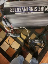
Apparently the earth ground being used as a 60Hz grid power ground and netural makes for a 60 cycle hum that strongly effects the field effect transistors (Earth ground Bias) MOSFETs and cause problems and issues in timing. Shorts in opposing FETs and general instability in operation is the results, have encountered this with several brands of off the shelf inverters as well, most that try a DIY system with off the shelf equipment and smoke the FETs don't have a clue why it failed.

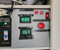
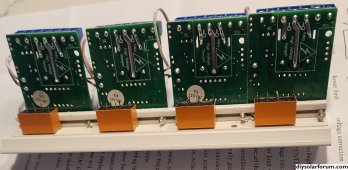
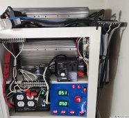
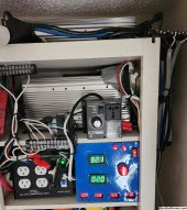
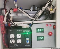
The combination of ISO transformers and the better 40N65 MOSFETs allows for extremely stable power production, you will be amazed with the stable operations, for example the moment the grid powered diode bridge was moved from the inverter case to the bottom of the secondary ISO transformer the system output more than doubled in amp flow.❤️

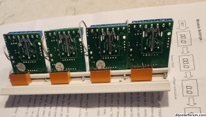
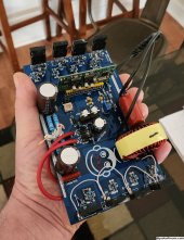
The next big improvement came from bypassed input resistors on the power board, board is designed for 380VDC input and with the our direct drive 180VDC input the 40N65 FETs can more than handle the the additional output amps. Also turning the potentiometer full clockwise sets the CPU for Maximum power after the soft start.

Also another bias has been noted when blending equal amounts of solar and grid based DC, the instructions refer to it as syncing from two sorces and refer to it as hot/cold cathode problem, The bias causes the production of static charges like a Marx generator and will destroy the diode bridge and FETs.

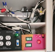
The static forms arcs that provide shorts across the silicone electronics till damage is done, the ISO transformers prevent all of this from happening.
All though the ISO transformers are a bit pricey have yet to find a low cost alternative that actually provide the same rock solid operation and safety!

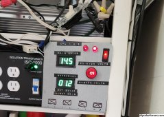
Have been in commercial electronics for a long long time, the stable output and pure sine power of this tiny power board is simply amazing, You need one or more.

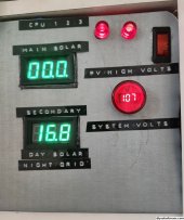
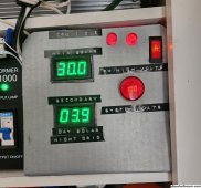
The hybrid grid support and voltage boosted solar system makes for more PV power in full sun and stable operations accross a wide range of solar sky conditions and loads.

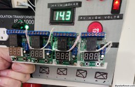
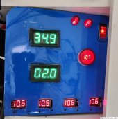
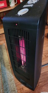
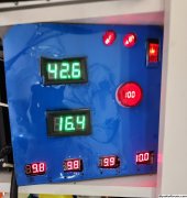
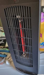
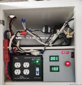
Beefing up the power board DC traces to the FETs and additional pure copper wires on the AC output traces make a difference you can see on a quartz tube heater. Maximum stability comes from just 4 of the 40N65 MOSFETs. 8 FETs can do more power but keeping 8 FETs in perfect sync is tricky, out of sync FETs will short out in opposing pairs.

More in a few days.

Best wishes
 

Attachments

  • 20230327_185219~2.jpg
    20230327_185219~2.jpg
    837.6 KB · Views: 5
Last edited:
Made it home safe.

Shut down tonight for big upgrades, expect up to 5 days to complete the updates.

Last shutdown was also for upgrades March 19th 2023

Successful shutdown, PV fuses and switches opened, secondary ISO transformer off, a few seconds later switched the power board CPUs to off.

Already ditched all the card board duct work and fully cleaned and oiled the ventilator fan and metal box assembly, base building block for new upflow adjustable metal duct work ventilator system.

More soon

Just remember a power production unit is only as strong as it's weakest link, building this project system correctly makes for a strong platform for your electronic stuff.

Perfect operation of the core power boards, thats more than than 8 month's of hard continuous daily use.

Making forward progress on the display and additional 4 voltage controlled relays accross the bottom, electrical is all headed the right direction.

More soon
 
Last edited:
Teaser photo of coming upgrades, file under things that make me smile.

Transfered first voltage controlled relay from a location 10 foot away, everything looks great.

Tomorrow the slim silver main inverter moves to the top shelf and all wire nuts will be eliminated being replaced with terminal strips, after that a push to install the combo inverter unit in the main space with the elimination of wire nuts on everything high voltage.

Third photo input and output terminal strips for all high voltage connections.
Terminal strips will be screwed to the cabinet and topped off with nice clear insulation snap on cover.
Fiber optic CPU indicators are on hold could not get the 2mm Fiber optic material needed for the 5 CPU power board status lights. The two indicators I have will show Main and Combo CPU main 16VAC power on.Slim silver Main inverter is sitting in it's new spot have an idea to make the terminal strips strong and good looking ?

Second blue display is all 4 voltage controlled relays function perfectly adding additional loads will be easy.

Last picture Combo unit sporting input and output terminal strips, making good progress top inverter near power up missing vent air system in progress.


More here soon
 

Attachments

  • 20231127_161502~2.jpg
    20231127_161502~2.jpg
    978.1 KB · Views: 3
  • 20231120_140155~3.jpg
    20231120_140155~3.jpg
    1.4 MB · Views: 4
  • 20231128_120620.jpg
    20231128_120620.jpg
    900.3 KB · Views: 3
  • 20231128_142108~2.jpg
    20231128_142108~2.jpg
    1.1 MB · Views: 3
  • 20231128_154631~2.jpg
    20231128_154631~2.jpg
    1.6 MB · Views: 4
Last edited:
Tomorrow a big push to get the vent fan and metal duct work installed, have a great idea to pull in air through the combo unit and blow air upwards through the main unit with a very compact fan assembly. Pictures

Next steps is install the combo and correct the wiring for startup.

Two more days to get my living room heater back.

Making forward progress, ventilator mounted in the space and is operational, getting excited, just need to not mess up the final wiring needed for restart.

Hope for a restart during the day tomorrow, lots to screw down yet to make things permanent.

More soon
 

Attachments

  • 20231128_205459~2.jpg
    20231128_205459~2.jpg
    638.5 KB · Views: 2
  • 20231129_120559~2.jpg
    20231129_120559~2.jpg
    1.2 MB · Views: 2
Last edited:
System successfully restored at 10AM still a ton of work to do and the combo unit has yet to be load tested.

Very happy at this point terminal strips helped with reconnecting the system properly ❤️

Combo unit is alive and well all 3 power boards are rockin ?, This is going to be fantastic 5 boards currently running at the same time can be controlled two different ways.10,000 watts capable premium green power boards at my command.

Last picture mail order kit #1 running the quartz tube heater on the first level from stage 3 of the combo unit successfully ❤️

Everything is glass fused on the inputs and outputs for safety, 15Amps or less use recommended sizes.

Note how the 4 voltage controlled relays basically follows the system voltage, not intentional but nice, the 1st voltage controlled relay is active and responding to moving clouds.

Still have wire nuts to remove and wire ties/wire supports to install, Generally everything headed the right direction.

More soon
 

Attachments

  • 20231130_101759~2.jpg
    20231130_101759~2.jpg
    984.9 KB · Views: 1
  • 20231130_101735~2.jpg
    20231130_101735~2.jpg
    687 KB · Views: 1
  • 20231130_101708~2.jpg
    20231130_101708~2.jpg
    890.3 KB · Views: 1
  • 20231130_111436~2.jpg
    20231130_111436~2.jpg
    621.9 KB · Views: 1
Last edited:
Going to shut down for a couple hours tomorrow morning to drill and screw down certain things also install wires ties.

Unit ran strong today.

Need to install three 5VDC pilot relays in the combo unit for CPU on/off the double pole design is needed to on/off the CPU because of the shared negative across all three power boards.

More soon
 
Last edited:
First look still very much in progress with wire nuts to be eliminated and wiring improvements ahead

System is fully operational, rainy day but solar is still running the lions share. Top 20 amp full scale, secondary 10amp full scale.

Ordered one more kit to get a replacement CPU for board #2, Board #1 is on the work bench for relay CPU control and independent system voltage monitoring. AWESOME!❤️

Testing revealed voltage controlled relays are fast and reliable for dumping loads and transfer signals to switch equipment impressive response time.

Much more soon.
 

Attachments

  • 20231201_121538~2.jpg
    20231201_121538~2.jpg
    1.1 MB · Views: 3
Last edited:
The sensor DC voltage for the 1st relay comes from a 11.7 volt AC output 120VAC input transformer to a diode bridge with filter capacitor and resistive load to cause the voltage to update continuously, this voltage is routed directly to the sensor terminals on the voltage controlled relay so you can switch things based on the power board output system voltage.

Although it is not important for the numbers to perfectly match this example comes close to matching the relays to the system voltage.

An 11.7 to 12volt output transformer will provide similar results.

It is dangerous to make adjustments on a running system, Voltage controlled relay saved the system yesterday, Absolutely amazing response to save a power board in full sun conditions.

More soon
 
Last edited:
Cloudy day but the system always manages to deliver lights, fans, electronics, and a stage 1 heater in the living room.

Also running a mini fridge, working perfectly, will in time improve the look of the terminal strip connections each has been pull tested but can easily be reworked to look better.

Going to proceed slowly from here on out, important not to mess anything up.
True dimond in the ruff live power system.

Best wishes

More soon
 

Attachments

  • 20231203_135026~2.jpg
    20231203_135026~2.jpg
    1,017.8 KB · Views: 1
Last edited:
Nice,
As we know you have oscilloscope can you measure signal before " L " or just after Fet?
Also do you know value of " L ",it should be 3mH?
Best
 

diy solar

diy solar
Back
Top