SomebodyInGNV
New Member
- Joined
- Jun 3, 2020
- Messages
- 183
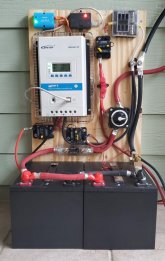
I finally have something to show for my inane questions in the past months. I have yet to install this in the front outside cabinet of my trailer but it's substantially complete. The terminal lugs may seem uninsulated because the shrink-wrap is clear.
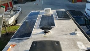
The panels are not yet installed. Right now I have 2 in series leaning on the wall outside the back door. Of course, it's a gloomy day.
 When installed there will be 4 x 180W Newpowa panels mounted flat on the roof in a 2S2P array. An 8AWG cable will travel down inside the front frame of the left front closet to the controller.
Smaller cables going down to the right will connect by a single 4AWG cable to the OEM converter. The black will go to a chassis ground immediately below the cabinet. I also upgraded the chassis ground to the power center to 4AWG. I'm not upgrading the WFCO charger/converter, instead depending on the solar system to charge the LFP batteries fully.
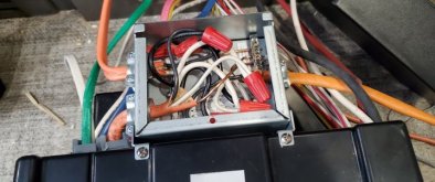
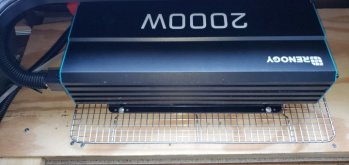
2/0 cables going up to the right will connect to a 2000W PSW inverter, about 1' away. It will connect to a 30A WFCO auto-transfer switch (below). It fits on the back of the power center making for an easy install and compact package.
The inverter remote switch will be close by. When the inverter is on, the AC and converter breakers will be off, so it will be well within the inverter limits. I also added a 15A circuit with a new outlet in the solar cabinet. If I upgrade the converter later, that circuit will be the power source.
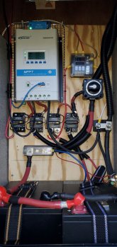
The Bluesea disconnect switch (I repurposed one I had) has 4 positions. I can cut off the inverter separately from the house/converter. The lower breakers isolate the SCC from the panels and battery.
The batteries are SOK 12V 100A with a max sustained discharge (in parallel) of 200A. They'll tolerate a higher surge to the Renogy inverter longer than the inverter will.
The panels are not yet installed. Right now I have 2 in series leaning on the wall outside the back door. Of course, it's a gloomy day.

Smaller cables going down to the right will connect by a single 4AWG cable to the OEM converter. The black will go to a chassis ground immediately below the cabinet. I also upgraded the chassis ground to the power center to 4AWG. I'm not upgrading the WFCO charger/converter, instead depending on the solar system to charge the LFP batteries fully.
2/0 cables going up to the right will connect to a 2000W PSW inverter, about 1' away. It will connect to a 30A WFCO auto-transfer switch (below). It fits on the back of the power center making for an easy install and compact package.
The inverter remote switch will be close by. When the inverter is on, the AC and converter breakers will be off, so it will be well within the inverter limits. I also added a 15A circuit with a new outlet in the solar cabinet. If I upgrade the converter later, that circuit will be the power source.
The Bluesea disconnect switch (I repurposed one I had) has 4 positions. I can cut off the inverter separately from the house/converter. The lower breakers isolate the SCC from the panels and battery.
The batteries are SOK 12V 100A with a max sustained discharge (in parallel) of 200A. They'll tolerate a higher surge to the Renogy inverter longer than the inverter will.


