diy solar

diy solar

Noob question - real world voltages

Stewfish

New Member
Joined
Oct 20, 2020
Messages
316
Dumb question.

There's a lot of info on how to calculate wiring sizes, controllers, etc based on the 2 different voltages, but I can't find info about what real world numbers will be on a sunny day. Is there a way you think about them to keep the differences in your head.

Is this how I should think about the differences?

Vmp - 30v
-is real voltage output when everything is connected/ closed curcuit
- lower volts used for wire calcs = bigger guage

VOC - 38v
-is max voltage when open, as in not in a closed circuit or producing power. Just measuring leads.
- higher volts + cold co = used for hardware choices/ calcs


So when I received my used panels I checked and was getting 36 point something volts (voltage is 30v, Voc 38, 250w, 60 cell solar farm panels. I had them leaning up against something on the ground. I now have them mounted and at the correct angle. I have the system hooked up to my charge controller in 3s to get 114v max plus cold Co. I'm not reading more than 90 volts even at the combiner box over the past few days since I finished everything. Why was I seeing 36 when checking the individualy from the their mc4 connectors vs being hooked up and lower voltage? I'm assuming they will run at 30v unless it gets cold out and drives the voltage up with cold co.
 
Last edited:
What you are seeing is completely expected, based on the specifications you gave above. The Voc is what you are measuring when you hold the electrodes to the bare MC-4 connectors. Once you have the panels under load, the voltage drops down to the Vmp, which in your case is 30V X 3 panels in series = 90V.

Keep in mind though that your controller can be exposed to the Voc even when everything is hooked up and connected. When your controller is working in PWM mode (yes, even if it is a MPPT), when the controller opens the circuit, the system is exposed to Voc. When the controller closes the circuit, just for a fraction of a second, all the electronics get exposed to the Voc till the current has a chance to drop back down to the Vmp.

So, everything is OK. Lean back and enjoy your power.
 
Dumb question.

There's a lot of info on how to calculate wiring sizes, controllers, etc based on the 2 different voltages, but I can't find info about what real world numbers will be on a sunny day.
You'll calculate wire sizes based on the amperes in the circuit, not the voltage

Don
 
You'll calculate wire sizes based on the amperes in the circuit, not the voltage.
Wire size from panels to SCC is calculated by.
Voltage
Amps
Distance

Connecting panels in Series for higher Voltage allows for smaller and cheaper wire.

 
Wire size from panels to SCC is calculated by.
Voltage
Amps
Distance

Connecting panels in Series for higher Voltage allows for smaller and cheaper wire.

Thanks guys, thats a different question.

My reference to.the voltage was to the lower voltage of Vmp vs the higher voltage of the Voc. Yes, It would as you guys both pointed out, change the voltage used for calcs in a series of three like I have.
 
What you are seeing is completely expected, based on the specifications you gave above. The Voc is what you are measuring when you hold the electrodes to the bare MC-4 connectors. Once you have the panels under load, the voltage drops down to the Vmp, which in your case is 30V X 3 panels in series = 90V.

Keep in mind though that your controller can be exposed to the Voc even when everything is hooked up and connected. When your controller is working in PWM mode (yes, even if it is a MPPT), when the controller opens the circuit, the system is exposed to Voc. When the controller closes the circuit, just for a fraction of a second, all the electronics get exposed to the Voc till the current has a chance to drop back down to the Vmp.

So, everything is OK. Lean back and enjoy your power.
This is what I was thinking, but wanted to make sure. Thanks for the extra details too, its good to know.
 
What you are seeing is completely expected, based on the specifications you gave above. The Voc is what you are measuring when you hold the electrodes to the bare MC-4 connectors. Once you have the panels under load, the voltage drops down to the Vmp, which in your case is 30V X 3 panels in series = 90V.

Keep in mind though that your controller can be exposed to the Voc even when everything is hooked up and connected. When your controller is working in PWM mode (yes, even if it is a MPPT), when the controller opens the circuit, the system is exposed to Voc. When the controller closes the circuit, just for a fraction of a second, all the electronics get exposed to the Voc till the current has a chance to drop back down to the Vmp.

So, everything is OK. Lean back and enjoy your power.
Is 147 voc (3×49) using notc value enough margin for a scc with Max Voc of 150V?
The scc an renogy aio claims over voltage protection as well.... Would my panels (at sea level, 52N, when cold no direct sun) ever see Voc Notc values? And voltage drop on my wire run will take that down to 142V max notc at the scc. Thank you for guidance
 
Last edited:
Is 147 voc (3×49) using notc value enough margin for a scc with Max Voc of 150V?
The scc an renogy aio claims over voltage protection as well.... Would my panels (at sea level, 52N, when cold no direct sun) ever see Voc Notc values? And voltage drop on my wire run will take that down to 142V max notc at the scc. Thank you for guidance
That would be too close for my comfort, but perhaps your over voltage protection may work, but I'd be afraid ;). Use a calculator like this one - https://spheralsolar.com/solar-panel-voltage-calculator/ - put in the lowest temperature your area might reach to see what your max VoC will get to in the coldest temps...
 
I personally allow 20% as the 'overhead' when it comes to the combined Voc's to the PVmax of the controller...
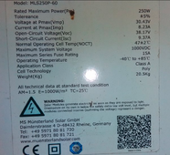
It is relatively common to see 10%-15% higher than the Voc rating at STC (which only applies with the panel at 25C, and illuminated by 1000W/m^2 as shown on one of my panels below)
1707233444918.png
In the 'wrong' conditions they can briefly peak higher (freshly cooled panels after rainfall, in summer, with almost continuous overcast, but with also having direct sunlight through a break in the clouds for example can take out a controller running too close to its limits)- as can snow at higher altitudes- direct and reflected sunlight from the snow and temps lower than 25C can really boost PV production...
(the hotter the panels are, the lower the output is- my panels here in summer run at 80C plus with air temps over 40C- in summer my output is basically down to winter outputs- dropping from their 250w rating to under 200w!!! (just when I want to run the A/C, I lost over 1/5th of their rated power!!!) Spring and Autumn are my peak generating times by far...
 
Is 147 voc (3×49) using notc value enough margin for a scc with Max Voc of 150V?
The scc an renogy aio claims over voltage protection as well.... Would my panels (at sea level, 52N, when cold no direct sun) ever see Voc Notc values? And voltage drop on my wire run will take that down to 142V max notc at the scc. Thank you for guidance
The voltage the panel outputs is very temperature dependent. That 147Voc number was determined at room temperature. At freezing, the voltage is likely to bump up to ~1.12X it's room temperature rating, and up to 1.25X at -40F. So, 147V becomes almost 165V on a frosty morning.

For a really accurate determination of what your panel string will put out at any given temperature, use Midnight's string calculator....
 
Back
Top