diy solar

diy solar

off grid system shock safety.

unikron

New Member
Joined
Sep 10, 2023
Messages
6
Location
Israel
Hi,
I'm playing with a small solar system, to get familiar with the concept, and later expand the system as I progress.
The system is not connected to the grid, and is totally separated.
Right now my system is made of:
3x100W solar panels in parallel(3 to 1 mc4 connector).
SRNE MPPT 40a/100v 12/24v.
Cheap 1500/3000W 12V to 220V inverter.
3 circuit breakers.
Busbars.
100a 12v gel battery.

Charge Flow is: solar panels -> 63a MCB(on both N/P) -> MPPT -> 50a thermal breaker(on positive) -> busbar -> 150a thermal breaker(on positive) -> battery.
Discharge flow is: Battery -> 150a thermal breaker(on positive) -> busbar -> inverter.

I want to understand what safety measures I need to take on the DC & AC sides to. avoid electric shock(mainly on the AC side).
A few notes:
The inverter has no grounding port, and I've opened the case and saw that only two wires are connected to the AC outlet output.
My area is not usually in lightning danger.
I want to upgrade the system(add on more battery in series, and replace the inverter) to 24v in the near future).

I'm a beginner, so maybe some of the info above my be confusing.
Your help is much appreciated.
 
"earth" = literally the earth with ground rod, OR the chassis of a vehicle.
"ground" = where the system potential is 0V.

Assuming 230VAC/50Hz.

Inverter has L, N and G AC output connections. If "G" is not present, there should be a grounding lug on the inverter chassis.

Panel frames should be grounded and earthed.
Inverter ground should be grounded and earthed.
12V (-) optionally grounded/earthed

N and G should be bonded together at only one point, i.e., near 0Ω resistant between them and 0V potential between. Some inverters do this internally, some don't. If it doesn't, you need to supply the bond.

@timselectric will correct, supplement or confirm the above. I'm not sure which. :)

Thanks for the detailed reply!

I forgot to mention a few details in my setup:
1. I live in a apartment building with a balcony(where the solar panels are).
2. The inverter doesn't have a ground lug, just -/+ on one side, and AC out on the other side.
3. yes 230VAC/50Hz
4. the only ground I have is the ground wire in the wall sockets, or the apartment main breakers panel.
5. 2 of the 3 panels are flex panels with no metal frame.
6. When looking inside the inverter, I saw only 2 wires go from the mainboard to the output socket(they must be N/L).

You've wrote to connect the N & G near 0 resistance, where would that be, and how to I know if my inverter does that internally ?
 
Thanks for the detailed reply!

I forgot to mention a few details in my setup:
1. I live in a apartment building with a balcony(where the solar panels are).
2. The inverter doesn't have a ground lug, just -/+ on one side, and AC out on the other side.

I would check the instructions. It should deal with grounding some way. It may be accomplished when you bolt the unit down to a grounded frame or such.

3. yes 230VAC/50Hz
4. the only ground I have is the ground wire in the wall sockets, or the apartment main breakers panel.

House ground is a good place to ground.

5. 2 of the 3 panels are flex panels with no metal frame.

Make sure those panels are a good match for each other.

If in series, their Imp value must be nearly identical.
If in parallel, their Vmp value must be within 10%.

6. When looking inside the inverter, I saw only 2 wires go from the mainboard to the output socket(they must be N/L).

You've wrote to connect the N & G near 0 resistance, where would that be, and how to I know if my inverter does that internally ?

With the unit ON, measure AC volts between L and N (230V), L and G (230V), N and G (0V).
With the unit OFF, measure resistance between N and G.

If there is no voltage between L and G and/or there is no continuity between N and G, then there is no N-G bond.

High likelihood that a small unit like this does not provide the N-G bond, and that's what you want, so you can tie into your apartment ground.

@timselectric must be on the road again. I really hope he steps in and takes over.
 
Hi :)

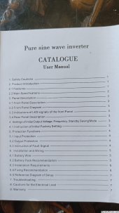
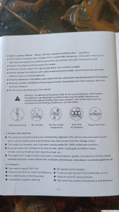
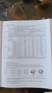
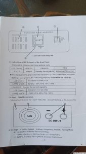
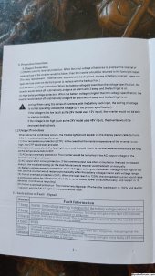
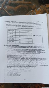
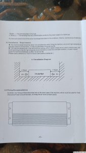
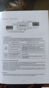
I've attached the instructions, I couldn't find any reference to grounding in them.
Tests
Unit on:
L and N - 231V
L and G - my multimeter just loops between checking resistance and doing nothing forever.
N and G - I get 2.2V and 2.4Hz
Unit off:
N and G - I get nothing

About my solar panels, they are pretty close in terms of V/A(less than 1 V/A).

How do I connect the N & G ?

Really appreciate your help.
 

Attachments

  • IMG20231106094115.jpg
    IMG20231106094115.jpg
    438.1 KB · Views: 1
  • IMG20231106094122.jpg
    IMG20231106094122.jpg
    541.1 KB · Views: 1
  • IMG20231106094128.jpg
    IMG20231106094128.jpg
    511.2 KB · Views: 1
  • IMG20231106094137.jpg
    IMG20231106094137.jpg
    428.1 KB · Views: 1
  • IMG20231106094145.jpg
    IMG20231106094145.jpg
    576.7 KB · Views: 1
  • IMG20231106094150.jpg
    IMG20231106094150.jpg
    572.8 KB · Views: 1
  • IMG20231106094156.jpg
    IMG20231106094156.jpg
    425.4 KB · Views: 1
  • IMG20231106094200.jpg
    IMG20231106094200.jpg
    514.9 KB · Views: 1
Last edited:
Back
Top