diy solar

diy solar

Off-Grid using Generator transfer switch.

k490

Solar Enthusiast
Joined
Nov 26, 2022
Messages
322
Location
Phoenix, Arizona
This is a design I came up with I have purchased one inverter to get 120V 3000 Watts of inverter output and 4680 watts of solar this year I want to wire everything for a future 2nd inverter next year. What I want to do is set this up in a shed using DIY battery Bank. I have an electronics background I have a technical certificate and worked for several years repairing power supplies and CRT monitors until I headed into IT world in the late 1990's. I have done some electrical work I have a decent understanding of house wiring 120V and split phase 240V.

The question I have is can I continue to use the N&G bond inside the service entrance of my house EG-4 disabled the software and removed the screw inside this inverter which use to have a relay switched the bond from input wiring to bonding inside the inverter. I have verified with a meter that the N&G inside the inverter is not connected which is what I want.

Will there be any issues with powering the EG-4 grid input and sharing the neutral with everything?
 

Attachments

  • transfer switch.pdf
    4.2 MB · Views: 24
  • EG4-3000EHV-48-Spec-Sheet.pdf
    2.9 MB · Views: 1
  • Off-grid.pdf
    21.3 KB · Views: 14
Last edited:
Have you reviewed these resource links yet?

Including both types, one of those types should match your type of stacking topology with the 3000EHV...

(Download the PDF file on the appropriate page, orange Download button in upper right corner)


General NEC information:
 
Last edited:
Thanks, I have watched those videos been reading the NEC 250 information. Is there anything to know about transfer switches I should know? I just ordered the 306C reliance controls. I'm assuming it will be like a load center where half the breakers will be tied to one phase other to the 2nd phase. With one inverter it will only have one phase working that's okay I probably only have 1 or 2 circuits connected in the house for now.
 
Last edited:
Thanks, I have watched those videos I have watched those been reading the NEC 250 information. Is there anything to know about transfer switches I should know? I just ordered the 306C reliance controls. I'm assuming it will be like a load center where half the breakers will be tied to one phase other to the 2nd phase. With one inverter it will only have one phase working that's only I probably only have 1 or 2 circuits connected in the house for now.

If you plan to move the N-G bond during different operating conditions (like for example if generator will be providing it while in inverter bypass, or anything like that, then you may need a transfer switch that can also open neutral.

Did you also look at the PDFs on those links? There are multiple ways to set this up, but generally NEC wants you to have only one N-G bond at a time (so you don't run risk of introducing objectionable ground current), and ideally it should be located as close to the active power source as possible.
 
Last edited:
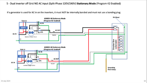
If I'm looking at it right, you'd want to review the schematic on Page 10 of the PDF: Grounding 6500EX-48 Dual Firmware.pdf

Would that be your suggested topology using the 3000EHV?


1703901865642.png
 
I guess it would be helpful to know if you have grid power, if you plan to create a separate breaker panel for your inverter loads, where you want a transfer switch, or if you can use the built-in ATS on the all-in-one inverters, etc.

Just look at all those wiring scenarios in the PDFs and try to identify the closest match to your desired topology, if your generator has a N-G bond, you can decide if you want to call it a separately derived system or not, and could disable the N-G bond in it (wire it more like an appliance), as long as you only have one N-G bond present in the system anywhere, during any of the operating modes.
 
I attached a diagram maybe you didn't look at it first post. Yes, the inverter grid input will be connected to Grid power. The outputs of the inverter will be going to a manual Transfer switch where I can direct power to 2-3 circuits in my home from the grid power, or inverter power. I can also change which circuits are on the inverter. By flipping different circuits in depending on the season. Summer I will be using 1000 watts in my shed for AC. I will send the other 1500 watts to my computers I want to keep those on inverter power, so they don't shut down during an outage.

Wintertime where I have an extra 1000 watts won't be needing the AC unit in the shed, I will direct that to the refrigerator for power savings. I really didn't want to buy the transfer switch would have been lot cheaper to just put in a small load center sub-panel that fed directly from the inverter would not give me the flexibility. This EG-4 3000 is a Voltronic inverter reading lot of threads lack of quality is why I want to have it.

I could have just connected everything to the EG-4 3000 inverter let the inverter pass grid power through. That's the way I probably will run most of the time. If I'm out of town and the inverter dies my wife here alone, she can go to the manual transfer switch flip everything to grid power until I get home, look at it. Even if I'm home I need to warranty replace it going to take time this way I don't have to do anything but flip those switches from gen to line on the Reliance transfer switch.

I will not be adding a N&G anywhere I will connect Neutral and Ground to the service entrance main breaker panel. The existing N&G bond will be the only bond I will be using it will pass through the inverter. The only reason I see anyone ever changing that would be in an RV, or portable power station where you plug things into it directly with extension cord.

Since I don't know the behavior of the 3000EHV, can you confirm if when the inverter is on (not in bypass), that the neutral on the AC output, is connected to the neutral on the AC input (since that is your only path from your N-G bond on the upstream main panel)? You would need to make sure that if a short occurred to ground, the ground current goes back to the N-G bond, so it can get back up to the neutral on the inverter output (via the input neutral) since it is the power source, to create enough current to trip the breaker...

If the inverter breaks the N-input from the N-output, then you might need to make it N-G bond for the circuits on the output of it (while inverter is running loads). I've also seen some guys use a jumper wire to jump the neutral of input to the neutral of output so they are always bridged.
 
Last edited:
Since I don't know the behavior of the 3000EHV, can you confirm if when the inverter is on (not in bypass), that the neutral on the AC output, is connected to the neutral on the AC input (since that is your only path from your N-G bond on the upstream main panel)? You would need to make sure that if a short occurred to ground, the ground current goes back to the N-G bond, so it can get back up to the neutral on the inverter output (via the input neutral) since it is the power source, to create enough current to trip the breaker...

If the inverter breaks the N-input from the N-output, then you might need to make it N-G bond for the circuits on the output of it (while inverter is running loads). I've also seen some guys use a jumper wire to jump the neutral of input to the neutral of output so they are always bridged.
I haven't powered the inverter yet not sure if it needs batteries before I can power it up, but I suppose if I take a computer power cable cut the end off, I could plug the grid input into a power strip on my bench. Then I can verify when it's powered on neutral is passed through when powered.

I have confirmed having no wires going to the inverter sitting on my bench Grid input and inverter output Neutral are connected confirmed by doing a continuity test.

Without batteries I can't confirm 100% that it's still passing through when the inverter is being powered by the batteries, or solar. I have batteries on order from China they won't be here until February, or March. I don't have any other 48V batteries around this inverter only works with 48V.

I'm going to wire everything up as I planned If I need to figure out how to pass the N line through from the input, I can do that later. I will check it as soon as I get the battery bank wired up still have lot to do before that happens.
 
I haven't powered the inverter yet not sure if it needs batteries before I can power it up, but I suppose if I take a computer power cable cut the end off, I could plug the grid input into a power strip on my bench. Then I can verify when it's powered on neutral is passed through when powered.

I have confirmed having no wires going to the inverter sitting on my bench Grid input and inverter output Neutral are connected confirmed by doing a continuity test.

It is typical that in bypass mode, the neutrals would pass through and be bridged. Just note, that even if power switch is on, it could be in bypass mode depending on the setting of USB, SUB, SBU, have to make sure the inverter is actually inverting while it's on, and check the continuity of the N's...


Without batteries I can't confirm 100% that it's still passing through when the inverter is being powered by the batteries, or solar. I have batteries on order from China they won't be here until February, or March. I don't have any other 48V batteries around this inverter only works with 48V.

I'm going to wire everything up as I planned If I need to figure out how to pass the N line through from the input, I can do that later. I will check it as soon as I get the battery bank wired up still have lot to do before that happens.

If you had four 12v batteries laying around, that could work, or even a 48v bench PSU that can at least power the idle draw current. Some of the inverters like this can run batteryless mode (only in single mode, not while stacking), but then they need a PV source in order to invert...
 
I don't have a PSU that goes to 48V nor do I have enough batteries. I can deal with this later when I do get the batteries. Right now, I'm working on mounting the panels, trenching conduit and pulling wire from my shed to the main breaker panel. I have an extra 1 1/2 conduit I put in when I remodeled my pool in case, I needed a 2nd conduit runs under concrete left a string in their back in 2007. Going to dig up dirt find the end attach it to mule tape pull that through. Plan is to pull set of 4 8-gauge hot leads set for grid input and grid output. One 8 Guage neutral and 8-gauge ground wire.

I could use 10 gauge this inverter max output is 25 amps. Later if I buy another one and do split phase it will still be 25 amps within 30-amp range. I always pull larger wire then needed my pool pump only pulls 8 amps I have 8 gauge. Nice thing about 240V wire doesn't have to be heavy wire for lighter loads.

I have been reading about the federal tax credit there doesn't seem require a system to be permitted. All that is require is that your generator power at your home. I know how the IRS works they just go with whatever you put down on your return if you get audited that is where your problems start.
 
Last edited:
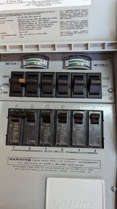
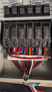
I received my batteries, and the Transfer switch did a little continuity testing. I found the transfer switch works like I thought. The same way a load center would work. Each 120V breaker alternates between phases. When I connect up one phase for now every other breaker will work which is okay, I only have a couple of circuits connected. The red and black wire is each phase going to the generator connection. Neutral and ground pass through like they should to the main panel.

PXL_20240102_233003025.jpgPXL_20240102_233752472.jpg
 
Last edited:
Can the inverter input and output share the same neutral wire going back to my main service panel? When I do a continuity test on the inverter the neutral for the input and output is connected inside the inverter. I'm trying to figure out the wire I need I want to upsize the wire if I want to put in a larger inverter.
 
Can the inverter input and output share the same neutral wire going back to my main service panel? When I do a continuity test on the inverter the neutral for the input and output is connected inside the inverter. I'm trying to figure out the wire I need I want to upsize the wire if I want to put in a larger inverter.

Was the inverter on or in bypass when you checked the continuity? I would double-check it both ways. It's fine to pass it through using a jumper if needed, as long as you understand if there are any other N-G bonds upstream, so one can be disabled if needed.
 
Was the inverter on or in bypass when you checked the continuity? I would double-check it both ways. It's fine to pass it through using a jumper if needed, as long as you understand if there are any other N-G bonds upstream, so one can be disabled if needed.
The N&G will be in the main service panel only it should pass through I haven't been able to confirm that yet soon I will. I'm just talking about the white neutral wires. This off grid inverter has an input and output I found the N connections had continuity between the two N input and N output. The reason I ask is my main service is 120 feet away from the shed. I will have the transfer switch right on inside of my garage right on the inside wall where the main is. Instead of running 4 hot wires, and 2 white, 2 green I want to run 4 hot two for input 2 for output and 1 white for N, and one green. I will confirm both N are connected when I get the inverter powered.
 
Back
Top