diy solar

diy solar

Open Ground when testing outlets on inverter

steviep19

New Member
Joined
Dec 26, 2019
Messages
141
When testing, all my outlets report Open Ground.

My inverter is properly grounded to a grounding rod outside, but I believe the reason for the Open Ground, is because inside my inverter the Ground & Neutral wires are not bonded. I'm wondering if there is a shock risk, if there was ever a short to the refrigerate or something metal.

It's also preventing sensitive equipment, like my Car charger to work of the Inverter, due to the open ground.

I purchased this inverter on ebay: https://www.ebay.com/itm/Power-Inve...-110V-120V-Car-Truck-Carvan-Boat/202875230081

It appears in this inverter neutral is not bonded inside the inverter to ground. Ground is instead connected to the chassis. I was thinking to resolve the problem, I should bond the Neutral & Ground wires.

I asked the seller and they responded back no. see below for their response

Dear,
good day,
no, we do not recommend to connect the ground to neutral, it will make the shell of the inverter have the electricity​


I'm thinking they're incorrect, and that's what I should do, but does anyone else have any experience neutral bonding / open ground on a system like this?

thanks in advance
 
You have to be careful with some of these HF inverters when joining neutral and earth. The ground terminal between the active/line/hot wire and neutral is not necessarily at 0 volts relative to neutral. Joining them will often result in the immediate and spectacular destruction of the inverter when it is turned on.

What I think you actually have across those three terminals, for affected devices, is a lower voltage replication of the USA's 240/120 split phase supply, ie 120/60 split phase. 120 across the hot terminals, 60 between hot and neutral. If you tie what you consider to be neutral to the indicated neutral you are actually shorting one phase and the inverter won't appreciate that. There are other designs that have a similar problem but with battery DC instead. Still quite explodey.

There are models of Reliable Power inverters that are know to have this problem. This may be an example of the issue, I've not actually watched the clip fully to know :)
 
Last edited:
gnubie,

Great find. I would have broken my inverter. I tested my inverter just like the person in the youtube video, and sure enough it does have a live ground. Looks like I won't be able to charge my car from this unit :(
 
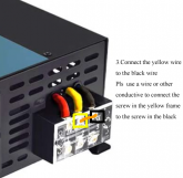
Just an update. I had contacted the seller again before posting the original post. They changed their mind, and sent me instructions to fix the grounding issue. I'm posting what they told me to do. I'll follow up with my results.

They want me to bond the neutral to ground, like I thought
s-l16001.png

They also want me to disconnect the below blue wire below. According to them that blue wire connects the yellow ground wire to the inverter shell.
s-l1600.png
 
I'm guessing they are telling you to rewire it like they send out of the factory now, break the internal ground so that the centre 'earth' terminal is no longer connected to chassis so that the centre earth on the terminal strip is floating.
 
USA power is center tapped 230VAC. The center tap is the neutral wire which is connected to earth and safety ground at the point it enters a building (main circuit breaker). The 120VAC in our wall outlets is from either of the two hot wires to neutral. 230 (for dryers and air conditioners) is from hot to hot.

Safety ground is present to ensure that if the hot wire ever got shorted to the metallic enclosure of the device it would trip the circuit breaker and prevent you from getting electrocuted.

For transformer isolated, 120 VAC inverters, grounding not an issue. The single secondary winding of the transformer does not have a center tap, but we don't need one. You are able to ground either end of the secondary winding and call it neutral and call the other end hot. You can switch which end is which without creating a problem.

With inverters that are not transformer isolated, the way you generate 120VAC is as follows.
  • Step DC battery voltage up to 200VDC.
  • Use pulse width modulation to chop the 200VDC into 120VAC.
  • The neutral output is connected to battery ground.
  • In this mode, grounding the neutral output is OK, because it is already at DC ground.
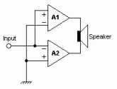
If you are trying to make the inverter cheaper, then you can get away with only using 100 VDC power supplies by driving both of the AC terminals in opposite directions, but with these inverters you can't connect either terminal to ground or you will destroy the inverter. This is the same as bridging audio amplifiers.

Bridge_amp.gif

The only reason people do things like this is because it is cheaper. High voltage rated parts cost more than lower voltage parts. So much so, that you can double the number of H-Bridge drivers and still save money.

I would not rewire your inverter. If you need a grounded neutral than you could add a 1:1 isolation transformer to the inverter output. Something like this. Going to cost a bit over $200.


If I was you I would return the inverter and buy a higher quality inverter than was designed correctly. Either one with a 200VDC power supply or better yet one with an isolation transformer.
 
Last edited:
HaldorEE,

Unfortunately, until recently I had no need for the outlet to be grounded, so I never checked. I purchased the inverter over 6 months ago, so no returns. I did however have an older 2kw version of the inverter with the same open ground. I performed the "fix" on it and it worked. The outlet is no longer reporting the open ground.

I think I'll still look into the Isolation Transformer for the main inverter, but I kinda like running this one separate.


The car charges at a rate of about 1500 watts. Between the Air Conditioners, Dehumidifier's and other household appliances already running off the main inverter, It makes sense to not add this large load.

For what I understand, the setup should be safe. If there was ever a short to the chassis, current would flow from the ground wire back to the inverter, back over to the bonded neutral wire, and trip the Circuit Breaker.
 
USA power is center tapped 230VAC. The center tap is the neutral wire which is connected to earth and safety ground at the point it enters a building (main circuit breaker). The 120VAC in our wall outlets is from either of the two hot wires to neutral. 230 (for dryers and air conditioners) is from hot to hot.

Safety ground is present to ensure that if the hot wire ever got shorted to the metallic enclosure of the device it would trip the circuit breaker and prevent you from getting electrocuted.

For transformer isolated, 120 VAC inverters, grounding not an issue. The single secondary winding of the transformer does not have a center tap, but we don't need one. You are able to ground either end of the secondary winding and call it neutral and call the other end hot. You can switch which end is which without creating a problem.

With inverters that are not transformer isolated, the way you generate 120VAC is as follows.
  • Step DC battery voltage up to 200VDC.
  • Use pulse width modulation to chop the 200VDC into 120VAC.
  • The neutral output is connected to battery ground.
  • In this mode, grounding the neutral output is OK, because it is already at DC ground.
If you are trying to make the inverter cheaper, then you can get away with only using 100 VDC power supplies by driving both of the AC terminals in opposite directions, but with these inverters you can't connect either terminal to ground or you will destroy the inverter. This is the same as bridging audio amplifiers.

View attachment 17418

The only reason people do things like this is because it is cheaper. High voltage rated parts cost more than lower voltage parts. So much so, that you can double the number of H-Bridge drivers and still save money.

I would not rewire your inverter. If you need a grounded neutral than you could add a 1:1 isolation transformer to the inverter output. Something like this. Going to cost a bit over $200.


If I was you I would return the inverter and buy a higher quality inverter than was designed correctly. Either one with a 200VDC power supply or better yet one with an isolation transformer.
Bought a EBAY cheap 3K inverter for my RV. It was not until I saw this post that I figured out what my problem was trying to get it to place nice with the rv. (powering the ac bus in the rv) I see now, that I will have to sell it and buy a different inverter. Thanks for this post.
Here is the inverter I should never have bought... https://www.ebay.com/itm/NEW-ADVANCED-PURE-SINE-WAVE-POWER-INVERTER-3000-6000-WATT-DC-TO-AC-12V-to-120V/392867791552?ssPageName=STRK:MEBIDX:IT&_trksid=p2057872.m2749.l2649
 
Very timely posting, I just purchased a Reliable 2500W inverter and was planning to backfeed my breaker panel. This will bond the neutral to ground.

I have watched the video multiple times, and it shows a 2nd Reliable with the neutral bonded. I wonder if the neutral naturally floats without bonding but still can handle being bonded.

I also sent an email to Reliable on June 27 but never received a response: “I am about to place an order for a 3000W 48V inverter. However I will connect the AC output to my breaker panel where the neutral wires are bonded. This will effectively ground the inverter neutral output. Some Reliable inverters have a "floating" neutral which measures 60V hot-ground and 60V neutral-ground. Hot-neutral will measure 120V. Please confirm the neutral can be connected to ground.”

Now wondering if I should likewise disconnect the chassis ground as per the instructions you received.
RV panel should not bond neutral to ground - If wired properly to ANSA -RVIA and NEC standards. Shorepower connection, when present is properly neutral bonded via primary panel board supplying the shorepower circuit. Otherwise neutral is independent of ground. Ground is fully floating and bonded to chassis. This is why well thought out RV systems use a fully wired DC return to battery negative to ensure circuit resistance is not an issue.

A UL 458 listed device will have provisions for maintaining proper neutral bonding and grounding during power inversion. IMO well worth the extra cost to be safe without work around solutions.
 
Just an update. I had contacted the seller again before posting the original post. They changed their mind, and sent me instructions to fix the grounding issue. I'm posting what they told me to do. I'll follow up with my results. They want me to bond the neutral to ground, like I thought

Please do. I don't understand their recommendation to jumper the neutral and ground wires.

The Reliable manual states “if the house neutral is combined with the ground, connect the black wire with it. Do not connect the inverter yellow wire with the black wire.” In my opinion this would make the case float at 60V and is totally dangerous.

I am going to do a similar modification:
  • Disconnect the case ground from the circuit board ground (blue wire).
  • Connect the yellow wire only to case ground.
This should let the circuit board float with the case being safely grounded:
 
Please do. I don't understand their recommendation to jumper the neutral and ground wires.

The Reliable manual states “if the house neutral is combined with the ground, connect the black wire with it. Do not connect the inverter yellow wire with the black wire.” In my opinion this would make the case float at 60V and is totally dangerous.

I am going to do a similar modification that should let the circuit board float with the case being safely grounded:
  • Disconnect the case ground from the circuit board ground (blue wire).
  • Will not connect or jumper the yellow (board ground) wire.
  • Connect the case ground lug to the ground terminal and breaker panel ground.
I tried every combination. The GFCI was not happy with any of them, and the inverter would get an error with one of them.
 
None of this sounds vaguely prudent.

I am not speaking from specific knowledge about this particular inverter. However the only reason I can think for grounding the inverter neutral to create a problem is if the inverter was designed with two bridged outputs with the hot and neutral both being actively driven in opposite directions.

If this is the case, the only safe way to ground the neutral in by adding an isolation transformer to the inverter output. Otherwise you are shorting out half of the inverter output to ground. If you isolate the battery ground from AC ground then it would work, but now you would have 60 VAC on your battery ground. That is not a good idea since everything connected to the battery negative is going to have 60VAC on it.
 
Just to add, an inverter with two driven outputs is cheaper in a HF inverter since it only requires the DC power supply voltages to be half as high. High voltage capacitors and transisters are a lot more expensive.

If you are doing a purely off grid system, you can let the outputs float although I wouldn't.
 
Thanks. I put the inverter on craigslist, hopefully will be able to recover a chunk of the cost. Tuition is never free. I will order a UL conforming one. Seems for 2k watts, I wont get away for less than $600 or so. Live and learn, right?
 
Thanks. I put the inverter on craigslist, hopefully will be able to recover a chunk of the cost. Tuition is never free. I will order a UL conforming one. Seems for 2k watts, I wont get away for less than $600 or so. Live and learn, right?
I was a bit resentful when I came to the realization that the cheap inverters probably wouldn't do what I want (power a microwave oven).

Look at it this way, if you buy a higher quality inverter it is also a lot less likely to let you down in use. And even the best inverter is still cheaper than a decent battery pack to drive it (unless you DIY).
 
HaldorEE,

I have 2kw and 5kw inverters by Reliable. I think the 2kw is the same one that you do. The 5k one that I posted having the live ground, I did not perform this fix on because I believe it will not actually fix, but the 2kw inverter I have did not have the live grounding problem. I performed the fix that they mentioned, and it resolved my grounding issue. I was able to plug in the Car Charger, and I tested it with an inline GFI breaker, and it passed. The 2kw inverter I have was able to power my microwave but just barely.

If you're running multiple things of the Inverter I find 5kw a good size. I have have had running a 12000 and 5000 btu Air conditions, the refrigerator, microwave, and various other smaller things running on it at the same time. Not on the same outlet of course without issue.

I've had no issues running my electronics of the 5kw inverter with that live ground problem. I've been powering them for about 8 months.
 
Back
Top