diy solar

diy solar

Other inverters with a 2.0 DC to AC ratio? Looking at Growatt MIN TL-XH-US

porchMan

New Member
Joined
Dec 13, 2022
Messages
8
I've been shopping around for inverters and I was pretty floored to find that the new Growatt MIN 3-11.4k TL-XH-US line has a 2.0 DC to AC ratio. Meaning I could stack 20k of panels on a 10k inverter, which after messing with PVwatts actually makes sense for my location and roof (Massachusetts, 160degree azimuth, 25degree roof pitch). I gain only a few hundred watts by having a bigger inverter!

So it's made me think, what other inverters have a 2.0 DC/AC ratio? or what other set ups could I consider to get a high DC/AC ratio? (There is 10k AC inverter limit for full net metering credits where I am)
 
Disclaimer: I don't know what the Growatt MIN 3-11.4k TL-XH-US has for HV DC filtering, but something you should know before jumping on what you think is great PV to AC output performance.

HF AIO inverters for PV to AC output power are pretty much same as battery-less GT inverters with the exception that cheap AIO's don't have enough HV DC filtering capacitors to remove 2x line frequency AC ripple current from PV path.

Single phase AC power has a sine squared power AC cycle period profile. PV panels need to have a constant MPP load to extract maximum power from PV panels. Having AC ripple current leak through on panels is like having MPPT point oscillating around the true MPPT point. You need significant energy storage (a lot of energy storage in capacitors) to supply the single-phase AC ripple current to prevent impacting MPP loading on PV panels.

Any AC ripple current that makes it through the SCC controller due to insufficient storage filtering will lower yield from PV panels.

Having twice the GT inverter mode PV to AC output power over battery powered inverter AC output is not very impressive if you lose a lot of PV panel efficiency due to ripple loading at MPPT.

Deye and SolArk have sufficient HV DC filter storage to prevent AC ripple current from showing up on SCC PV panel loading.
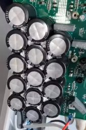
Each of these fourteen HV DC filter capacitors are 1000 uF, 315 wvdc rated capacitors.

This is one of the things you are paying extra $$ for.

Deye HV DC filter caps.jpg


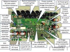
This is a Sunny boy battery-less GT inverter (5kW) with its HV DC filter 'smoothing' capacitors.

Sunny Boy PCB pict.jpg


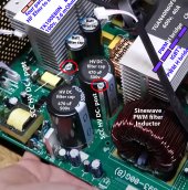
This is what a typical cheap 5 kW HF AIO inverter has for HV DC filtering. At their maximum PV power input directed to AC output, they have a lot of AC ripple leakage to PV panels reducing panel yield.

MPP PIP5048 board HV caps.jpg
 
Last edited:
Disclaimer: I don't know what the Growatt MIN 3-11.4k TL-XH-US has for HV DC filtering, but something you should know before jumping on what you think is great PV to AC output performance.

HF AIO inverters for PV to AC output power are pretty much same as battery-less GT inverters with the exception that cheap AIO's don't have enough HV DC filtering capacitors to remove 2x line frequency AC ripple current from PV path.

Single phase AC power has a sine squared power AC cycle period profile. PV panels need to have a constant MPP load to extract maximum power from PV panels. Having AC ripple current leak through on panels is like having MPPT point oscillating around the true MPPT point. You need significant energy storage (a lot of energy storage in capacitors) to supply the single-phase AC ripple current to prevent impacting MPP loading on PV panels.

Any AC ripple current that makes it through the SCC controller due to insufficient storage filtering will lower yield from PV panels.

Having twice the GT inverter mode PV to AC output power over battery powered inverter AC output is not very impressive if you lose a lot of PV panel efficiency due to ripple loading at MPPT.

Deye and SolArk have sufficient HV DC filter storage to prevent AC ripple current from showing up on SCC PV panel loading.
Each of these fourteen HV DC filter capacitors are 1000 uF, 315 wvdc rated capacitors.

This is one of the things you are paying extra $$ for.

View attachment 125035


This is a Sunny boy battery-less GT inverter (5kW) with its HV DC filter 'smoothing' capacitors.

View attachment 125041


This is what a typical cheap 5 kW HF AIO inverter has for HV DC filtering. At their maximum PV power input directed to AC output, they have a lot of AC ripple leakage to PV panels reducing panel yield.

View attachment 125036
Hmm very interesting, thanks for the excellent explanation! Do you think that is the reason they have made the DC limit so high? They expect losses from poor mppt?
 
It's relatively cheap to do so. More battery powered inverter power is what costs a lot more to do.
 
Single phase AC power has a sine squared power AC cycle period profile. PV panels need to have a constant MPP load to extract maximum power from PV panels. Having AC ripple current leak through on panels is like having MPPT point oscillating around the true MPPT point. You need significant energy storage (a lot of energy storage in capacitors) to supply the single-phase AC ripple current to prevent impacting MPP loading on PV panels.

Any AC ripple current that makes it through the SCC controller due to insufficient storage filtering will lower yield from PV panels.


This is a Sunny boy battery-less GT inverter (5kW) with its HV DC filter 'smoothing' capacitors.

5kW Sunny Boy, 3.35Vrms ripple riding on 398VDC


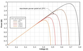
The watts/volts curve of PV is pretty flat, so +/-1% voltage is negligible. Maybe +/-3% before it starts to roll off.
Larger capacitors, less ripple, less heating, longer life. That's probably the bigger difference.

1671245727656.png
 
5kW Sunny Boy, 3.35Vrms ripple riding on 398VDC
Just have to stay above the maximum AC sinewave voltage peak for AC output, like 240vrms x 1.41 = 339vdc plus some margin for PWM H-bridge loss and highest spec limit on grid AC voltage. 260 vac max grid voltage would be 368vdc plus H-bridge and PWM filter loss margin.

When PV array Vmp gets near the high side voltage limit is where HV DC ripple valleys due to AC cycle peaks in current starts to really matter as HV DC ripple dips must always stay above maximum Vmp. This happens if HV DC smoothing capacitors are not large enough.

The reason I put the Sunny Boy GT and Deye pictures in was to show the dramatic difference between their HV DC smoothing capacitor banks and the feeble amount HV DC smoothing capacitors in cheap AIO inverters. With battery inverter active they can cheat by using battery power to fill in the ripple voltage dips in HV DC.

Chinese HF AIO inverters play a lot of gamesmanship with their specs. Maximum efficiency is when Vmp is close to HV DC bus so SCC boost converter is doing little work to boost up the Vmp voltage at a relatively low PV and AC output power draw to minimize losses and avoid ripple MPP loading showing up on panels.
 
Last edited:
Just have to stay above the maximum AC sinewave voltage peak for AC output, like 240vrms x 1.41 = 339vdc plus some margin for PWM H-bridge loss and highest spec limit on grid AC voltage. 260 vac max grid voltage would be 368vdc plus H-bridge and PWM filter loss margin.

Assuming pure buck architecture. Some must be buck-boost to allow 100Vmp. At a cost to efficiency? But they're pretty efficient. Maybe high-frequency transformer rather than actual buck-boost (inverting) switcher architecture.


When PV array Vmp gets near the high side voltage limit is where HV DC ripple valleys due to AC cycle peaks in current starts to really matter as HV DC ripple dips must always stay above maximum Vmp. This happens if HV DC smoothing capacitors are not large enough.

The reason I put the Sunny Boy GT and Deye pictures in was to show the dramatic difference between their HV DC smoothing capacitor banks and the feeble amount HV DC smoothing capacitors in cheap AIO inverters. With battery inverter active they can cheat by using battery power to fill in the ripple voltage dips in HV DC.

Yes, lots of caps. Anybody ever had a massive HV cap bank to cheap inverter as upgrade?

LF battery inverters have to draw from battery every cycle; capacitors can't fill that in because they can't ripple (battery takes over.)
Any inverter with HV rail can let capacitors ripple to ride through each half cycle.

That's probably where surge limitation comes from, only what boost can deliver.
Higher voltage in caps can deliver for a while, but reduces efficiency waiting forever for a surge.
 
Assuming pure buck architecture. Some must be buck-boost to allow 100Vmp. At a cost to efficiency? But they're pretty efficient. Maybe high-frequency transformer rather than actual buck-boost (inverting) switcher architecture.


Yes, lots of caps. Anybody ever had a massive HV cap bank to cheap inverter as upgrade?

LF battery inverters have to draw from battery every cycle; capacitors can't fill that in because they can't ripple (battery takes over.)
Any inverter with HV rail can let capacitors ripple to ride through each half cycle.

That's probably where surge limitation comes from, only what boost can deliver.
Higher voltage in caps can deliver for a while, but reduces efficiency waiting forever for a surge.
The present offering of LF AIO inverters have PV power converted directly to battery, then LF inverter creates the AC output with power drawn from battery node.

They have more loss from PV to AC output, compared to HF inverters, and puts the 2x AC grid frequency ripple current on batteries. Batteries are effectively a large capacitor bank.

This is why DC coupling (PV power injected to batteries) is not a good choice for exporting PV power to grid. The battery ripple current does stress the batteries and shortens their lifespan when you have long term grid power export.


You might be able to add HV DC filter capacitors to a HF inverter but there is a good chance of creating a feedback control stability problem with battery to HV DC converter. The HV DC voltage regulation control loop must be designed for having large output capacitors.

The large capacitance on HV DC slows down the control loop which is opposite what the cheap HF AIO have with their fast feedback loop to make up for lack of output capacitors to allow battery to HV DC converter to fill in for AC ripple voltage dip on their limited HV DC capacitance.

The idea AIO inverter, in my opinion, would be a LF inverter with an AC coupled internal PV GT inverter that injects AC directly on LF inverter AC output, with direct hardwired control over PV GT inverter operation. This solves the off-grid issue with sudden excess PV power that separate PV GT inverter units AC coupling have when a large house load is switched off. No need to rely on slow reacting frequency shifting to limit PV GT inverter output.
 
Last edited:
True, stability. Then you could slow down response of boost converter. Would be easy if analog, not if embedded firmware.

You might pull off that fast control of GT PV with datacom to external inverters. Sunny Boy with Speedwire interface can be so controlled (for limited or zero export.) I haven't tried it yet but maybe some day. I was thinking of CT and limit export to grid, also backfeed to house through Sunny Island (so I can have GT PV wattage 2x battery inverter wattage.) For your idea, CT on output of battery inverter rather than input. Or output and input, allowing backfeed to grid when present but limiting what has to be stuffed into battery when off-grid (or just enable limit when status is "off grid")

What I don't get is why Volts/Watts doesn't take care of the load-dump situation.
 
So it's made me think, what other inverters have a 2.0 DC/AC ratio?
Some input to your specific question, when I was looking around researching before starting to build my system 14 montuhs ago I saw quite a few inverters that would do 2 DC/AC ratio. I am using the Growatt MIN 3-11.4k TL-XH-US, but some examples of inverters that will do a ratio of 2 DC/AC are the SolarEdge SE****H-US and the Fronius Primo line. Of course there are big differences between these inverters, but they all can take a ratio of 2 or more depending on which one.
 
Some input to your specific question, when I was looking around researching before starting to build my system 14 montuhs ago I saw quite a few inverters that would do 2 DC/AC ratio. I am using the Growatt MIN 3-11.4k TL-XH-US, but some examples of inverters that will do a ratio of 2 DC/AC are the SolarEdge SE****H-US and the Fronius Primo line. Of course there are big differences between these inverters, but they all can take a ratio of 2 or more depending on which one.
Great thank you!
 
If GT PV is producing 4kW to match a 4kW load and the load suddenly switches off, apparently problem is HF battery inverters can't suck down the power while gradually shifting frequency?
But if load is removed, wouldn't voltage rise cause GT PV inverter to immediately decrease power delivered?
Or is Volts/Watts also designed to react slowly?
AC output voltage is regulated, and any rise amount is limited to prevent other destructive effects on inverter or attached loads. PV GT inverters allow some amount of grid voltage surges for a limited time period.

All statements below pertain to when grid is not available.

Obviously, inverter cannot absorb a sudden PV GT inverter back surge beyond the inverter's surge power limit. Then there is the stress and logistics of battery management. Most AC couplable capable hybrid inverters limit the SoC amount on battery to keep battery impedance low in preparation to absorb a back surge. If back feed surge causes battery voltage to rise above maximum DC voltage input limit of inverter, the inverter has no other choice but to shut down, dropping all AC loads.

Freq shifting PV GT inverters can take a few hundred milliseconds to up to a couple of seconds to react and reduce GT PV power. Inverter cannot shift its frequency too fast as you might have AC motor loads on AC output which could kick back current if frequency is shifted too fast. This reaction time is fine for casual clouds going by, but when a large PV power excess shows up all of a sudden due to large house load being shut off it is a tougher problem. A lot of damage can be done to inverter in that amount of time.

You never know when grid might go down so an AC coupled inverter that allows a pass-through to grid more power than inverter/battery can absorb is running in a risky situation. SolarArk and Deye have a parachute. They use the generator pass-through relay to pull the plug on PV GT inverters if it gets into trouble with excessive back feed.
 
Last edited:
Back
Top