diy solar

diy solar

Parallel 48v battery method...

TimC

WI/UP Border
Joined
Apr 17, 2020
Messages
139
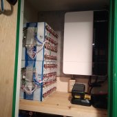
I've got two 48v 75 aHr batteries that I am going to wire in parallel to a Growatt 3000ES.

Which is the preferred method, or does it not make any difference?

A - run Pos and Neg of each battery to two bussbars (+ and -) and then a single wire from bussbars to breaker and then Growatt
B - run Pos to Pos on batteries, Neg to Neg on batteries, then a single Pos and single Neg from one battery to the breaker and then Growatt.

My load(s) are not big. Largest draw will be a 120v, 1.4kW, 12a Level 1 EV charger. I will not be pulling more than 2.0kW at one time.

Thanks, Tim
 
Thanks Sun Eggo. That's a comprehensive document.

Looks like one correct way is to run from each battery to a Pos and a Neg Bussbar and then to the inverter.
 
For only two batteries:

C. Connect the two battery positives. Connect the two battery negatives. Connect positive of one battery to breaker to Growatt. Connect negative of other battery to Growatt (with possible shunt in between).

This is the "diagonal" method shown the Unlimited Wiring document linked earlier.

That's similar to your B option (avoid) but with the important difference that you must not connect both wires from the Growatt to the same battery. One wire to one battery, other wire to the other battery. That will help keep them in balance.

Option A has the advantage of being more modular. Each battery is separate and can be removed without affecting the system. Or you can more easily add a 3rd battery. If you go with option A be sure the two positive wires from the batteries to the positive bus bar are the same length as each other. Then make sure the two negative wires form the batteries to the negative bus are the same length as each other. The gives each battery the same resistance each the others to maintain balance.
 
Option A has the advantage of being more modular. Each battery is separate and can be removed without affecting the system. Or you can more easily add a 3rd battery. If you go with option A be sure the two positive wires from the batteries to the positive bus bar are the same length as each other. Then make sure the two negative wires form the batteries to the negative bus are the same length as each other. The gives each battery the same resistance each the others to maintain balance.

Do the positive and negative wires from each battery to the bus bar have to be the same length as each other? Or can you have a 4" positive wire on battery one to the bar, 6" to positive on battery two. Then 6" negative on battery one and 4" negative on battery two? I assumed it only mattered that the total circuit length was the same.

I'm not trying to be obnoxious, just wanting to wrap my head around it correctly.
 
Do the positive and negative wires from each battery to the bus bar have to be the same length as each other? Or can you have a 4" positive wire on battery one to the bar, 6" to positive on battery two. Then 6" negative on battery one and 4" negative on battery two? I assumed it only mattered that the total circuit length was the same.
Yeah, ultimately you need the total circuit path to be the same length for each battery. Seems simpler to have the positive leads the same as each other and the negative leads the same as each other but if your setup prefers a different approach that still results in equal total path lengths then I see no issue.
 
Yeah, ultimately you need the total circuit path to be the same length for each battery. Seems simpler to have the positive leads the same as each other and the negative leads the same as each other but if your setup prefers a different approach that still results in equal total path lengths then I see no issue.
OK, I get the theory that the + and - wires should be of equal length. But what about all the length of negative wire to the BMS and then out to the battery terminal? If you are equalizing lengths shouldn't that be a consideration?

I'm estimating that the extra length going through the BMS and then to the post is close to 12".

Are you saying your cabling from your negative battery bus bar to your inverter is 12" shorter than the cabling going from positive battery bus bar to the inverter? That's fine.. those don't need to be equal length.

What should be equal length is the total cable circuit path positive/negative for each battery to the positive/negative battery bus bars to encourage each battery to be "equal" and get used the equally by the inverter.
Longer, not shorter...

I'm referring to the negative wires coming off the battery negative to the BMS, through the BMS and then to the battery posts. This length is X2 as I have two 48v batteries in the bank. At that point the 4awg going to the Growatt is equal length with the positive wires.

So I'm referring to approximately two feet of wire, BMS and wire before the battery posts on the negative side. On the plus side there is only about six inches.

When we read "equal" are we referring to "not excessively different lengths" or literally equal? If it's strictly equal does anyone consider the length and resistance through the BMS.
 
@Tim C.

You keep saying BMS and battery negative.. are you running a custom built battery using raw cells, or a prepackaged lifepo4 battery using an internal BMS that you aren't supposed to mess with?
 
Yes, I'm messing with the BMS...

I'm still scratching my head on how to finish wiring and end up with a diagonal pos and neg across the two battery bank. Not as straight forward as it seems with a prepackaged set.


20220730_192604.jpg
 
Those banks appear identical, so the only lengths that matter are positives and negatives cables to the busbar

You want equal resistance to each battery.
 
Those banks appear identical, so the only lengths that matter are positives and negatives cables to the busbar

You want equal resistance to each battery.
OK. Maybe thinking too hard about this but when folks here say equal I think there's some +/- factored into it. So the distance through the BMS to each battery post is not considered?
 
OK. Maybe thinking too hard about this but when folks here say equal I think there's some +/- factored into it. So the distance through the BMS to each battery post is not considered?
Correct me if I misunderstood anything, but both batteries appear the same.
So, the bms cable length should be the same, no?
 
I think I see your confusion...
The positive and negatives don't have to be the same...
The negative and negative on each battery needs to be the same.
And the positive and positive needs to be the same.
 
@Supervstech is amazing, and I don't want to muddle up anything he is trying to tell you.

Looking at your exposed BMS innards, the BMS manages the cell balances internally and the lengths of the cables going to each cell isn't your concern, that's why it has all those balance leads going to each cell.

I'm assuming when you took these apart, or built them, however they got this way, that the cables running from the BMS negative and positive EXTERNAL OUTPUTS are the same for each complete battery to the "POST". If that's the case, you are good for the innards of the battery and don't have to worry about anything behind the battery posts. If they aren't, and you replaced the cables behind the posts or made your own cables for them, then yes, those would need to be the same length for each "battery" or you will end up possibly having imbalances or uneven battery wear.

Your BMS can only perform cell balancing for anything behind the POST to BMS wires, where the thick external wires attach to the BMS. Anything beyond that point needs to be the same total length for the circuit as the BMS cell balancers can't control what they don't have access to.

Because the BMS only handles the combined input/output voltage of the total battery on the POST outward side of things that is where it's important you have equal cable circuits on the outside to make sure to the best of your ability that each battery receives the same voltage and amperage.

It doesn't matter how the current gets to them, one could have a really short thin cable, one could have a really long thick cable. What matters is they each get the same current in the end.. fair is fair. It's just easier if the cables from the bus bars to the posts are exactly the same.
 
I think I see your confusion...
The positive and negatives don't have to be the same...
The negative and negative on each battery needs to be the same.
And the positive and positive needs to be the same

I think I understand except on a two battery bank "the same" doesn't apply does it? There's only one parallel wire. On a three battery bank the "same" applies to the parallel wires?

Here what I'm planning. The 4awg from B1 to B2 is 19". The 4awg from B2 to the bussbar is 24". Then neg bussbar to the inverter/charger the 4awg is 24"

The positives are the same lengths except instead of a bussbar they go to a 100a circuit breaker then the inverter/charger.

I can draw a diagram if that doesn't make sense.
 
I think I understand except on a two battery bank "the same" doesn't apply does it? There's only one parallel wire. On a three battery bank the "same" applies to the parallel wires?

Here what I'm planning. The 4awg from B1 to B2 is 19". The 4awg from B2 to the bussbar is 24". Then neg bussbar to the inverter/charger the 4awg is 24"

The positives are the same lengths except instead of a bussbar they go to a 100a circuit breaker then the inverter/charger.
There is more than one way to wire together two (or more) batteries in parallel.

With just two batteries where the two batteries are directly wired together in parallel there is no need to worry about any wire lengths at all. The only requirement is that the two wires going to "the system" from the batteries are each connected to a different battery. This my "option C" presented in post #4.

Wiring like your option A is where proper wire lengths matter.
 
Gotcha. Thanks and sorry for the confusion. I'm taking my time and missing a lot of sun trying to build this right. You guys are a big help... especially when I ask intelligent questions : )
 
Back
Top