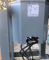
diy solar

diy solar

PG&E transformer upgrade: why?

@Hedges would you be so kind as to draw a simple diagram of what you mean and where the double-neutral current is flowing? I am picturing what you are saying in my head, but, I'm coming up with different numbers than you are.
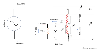
The way I get it is that all of the neutral current has to circulate on the full length of the secondary coil in an RMS context; the positive sequence current goes one direction and the negative sequence goes the opposite. So, the coil is actually loaded 2x for all 120V loads, plus the 240V loads.
 
Last edited:
If you are feeding the utilities transformer with a 240 volt 200 amp backfeed all that power will still flow on L1 and L2. You could feed this back to the utility even if you did not have a neutral wire. The neutral is only needed for 120 volt circuits. It's 48,000 watts. The reason is that the current on each leg is 180 degrees out of phase with the other leg. That is why it cancels out. If the current was on the same phase then indeed the 200 amps would add together on the neutral, but that's not how 240 volt current works.

Now if a neighbor were to consume all that power you push into the transformer on a single 120 volt phase, they could draw 400 amps out of the transformer. It would flow out through one of the hot legs and back through the neutral. The transformer is then working essentially as a step down transformer. Half the voltage means twice the current since the power is conserved. 200 * 240 = 400 * 120. But again that 400 amps is not going to flow on the neutral wire going into your house. Your neighbor would need to have a 400 amp service and consume all that power on a single leg in order to get 400 amps on his neutral wire. So 24 * 2000 watt hair driers all on the same Hot Leg would do the job. If your neighbor plugged 12 hair driers into each leg, then he would also have 0 current on the neutral.

You are correct when you say the current on the neutral is the IMBALANCE. When you push a 240 volt source back to the grid, you have zero imbalance. Your neutral will have zero current.
If your neighbor can have a 400 amp 120vac load, what happens if you have one at your house?
Sure, your pushing out 240, but like you said, there's nothing produced in the neutral by Hedges solar.
 
If you are feeding the utilities transformer with a 240 volt 200 amp backfeed all that power will still flow on L1 and L2. You could feed this back to the utility even if you did not have a neutral wire. The neutral is only needed for 120 volt circuits. It's 48,000 watts. The reason is that the current on each leg is 180 degrees out of phase with the other leg. That is why it cancels out. If the current was on the same phase then indeed the 200 amps would add together on the neutral, but that's not how 240 volt current works.

What happens if you have 100A of backfeed at 240v and 200A consumed on one L1? 100A two pole OCPD

That would be 100A from Utility on L1
100A to Utility on L2
200A to Utility on N
 
If we consumers only draw power from the grid, utility transformer is an isolation transformer. But if we backfeed power while anyone draws single-phase load, we use it as an auto-transformer (plus isolation for any power flowing to or from primary side.)
Wait a second, that is true for a traditional autotransformer, but the utility transformer acts as a balanced auto-transformer. There is no current flowing on the primary side if total load matches total generation on the secondary. The utility isn't acting as a buck/boost transformer to derrive a neutral.

There is a minor effect with harmonics, but for a balanced consumer with resistive loads and a "perfect" sinewave microinverter wired 240V half the loads will cancel the other half. All that gets back to the utility transformer is the imbalance net of line loads along the way.
 
If loads exactly equaled PV production on secondary of utility transformer, no current would flow in the primary. Exactly as if there were no primary windings, just an auto-transformer (give or take losses and no-load current.)

If all PV inverters were 240V, and all loads were 120V and on just L1, then transformer neutral current would equal transformer L1 + L2 (which would both be same current, but on in-phase delivering power and the other out of phase receiving power.)

If all the loads were at houses further away from transformer than PV, then both L1 and N to those houses would carry the double current and L2 to those houses would carry zero.
If all loads were between transformer and PV, then N would carry double current from transformer to loads. L1 and L2 would carry single current from PV. L1 would carry single current from PV to loads, and L1 would carry single current in opposite direction from transformer to loads.
 
If you are feeding the utilities transformer with a 240 volt 200 amp backfeed all that power will still flow on L1 and L2. You could feed this back to the utility even if you did not have a neutral wire. The neutral is only needed for 120 volt circuits. It's 48,000 watts. The reason is that the current on each leg is 180 degrees out of phase with the other leg. That is why it cancels out. If the current was on the same phase then indeed the 200 amps would add together on the neutral, but that's not how 240 volt current works.

True for isolation transformer with source on primary, split-phase loads on secondary.
Not true for split phase auto-transformer. The current on each leg is not 180 degrees out of phase, it is in phase. Otherwise, zero current flows through transformer.

The "neutral carries difference between L1 and L2" that you learned is a special case, where power is delivered magnetically, a moving magnetic field forcing current to flow same directions in both halves of secondary winding. Without a field delivered by primary, no current moves in secondary. Without a load on secondary, no current moves in primary.

Now if a neighbor were to consume all that power you push into the transformer on a single 120 volt phase, they could draw 400 amps out of the transformer. It would flow out through one of the hot legs and back through the neutral. The transformer is then working essentially as a step down transformer. Half the voltage means twice the current since the power is conserved. 200 * 240 = 400 * 120. But again that 400 amps is not going to flow on the neutral wire going into your house. Your neighbor would need to have a 400 amp service and consume all that power on a single leg in order to get 400 amps on his neutral wire. So 24 * 2000 watt hair driers all on the same Hot Leg would do the job. If your neighbor plugged 12 hair driers into each leg, then he would also have 0 current on the neutral.

You are correct when you say the current on the neutral is the IMBALANCE. When you push a 240 volt source back to the grid, you have zero imbalance. Your neutral will have zero current.

If my house had 240V 200A backfeed at 240V, my house would have zero current on neutral.
If I connected 48,000 watts of 120V load entirely between L1 and N on my breaker panel (while backfeeding 48,000 watts of 240V PV from far end of panel in violation of 120% rule), my L1 and L2 breakers would each carry 200A. My neutral wire would carry 400A.

If my house does the backfeeding and two neighbors each have 24,000W 120V 200A load on L1 (for total 48,000W between them), I will have zero neutral current, each neighbor will have 200A neutral current, utility transformer and overhead power lines will have 400A neutral current. Whether overhead L1 has 200A or 400A will depend on who is closer to transformer, me or the two neighbors.

If you don't agree with this, don't analyze by writing prose. Draw a schematic with auto-transformer, 48kW 240V source, 48kW 120V load. Then analyze power and current flow.
 
@Hedges would you be so kind as to draw a simple diagram of what you mean and where the double-neutral current is flowing? I am picturing what you are saying in my head, but, I'm coming up with different numbers than you are.

Don't listen to your lying head.
It is easy to think the transformer should do something, and this took me a while to wrap my brain around.
Just apply Kirchhoff's Current Law. Or consider power flow and calculate amps based on volts and watts.

Seeing the schematic with your eyes makes it so much easier:

Auto-transformer current.png

The key is that current will only flow in one winding of the transformer if there is current flowing opposite direction in other winding.
Apply a load to the neutral, then current is allowed to flow in the directions shown.
 
Overhead Upgrade:


View attachment 172180

"You may be eligible to deduct a $1,918 allowance from the total cost of your electric service if you are upgrading your panel."
Is this allowance restricted to main service panel upgrades because of PV/NEM installs only? I recently upgraded my panel from 100a to 200a service and want to know if I can qualify for this allowance???
 
The isolation transformers I've got have separate windings, each with two flying leads. Wired in series, the two leads forming neutral are sufficient.
Problem would be if I brought out neutral with single wire of same gauge, and tried to use the full VA capability of the transformer. Two separate wires landing on breaker panel neutral busbar would do, or one wire of double ampacity. (inventory for experiments and future projects, not installed yet.)

I think most autotransformers are rated with the impressive VA of a 120V or 240V load that can be supported. One rated 3000 VA can actually transfer just 1500 VA without overheating, but in a buck-boost configuration, that's all it is called on to do. The other 1500 VA comes from the source. e.g. in boost configuration, an inverter delivering 3000 VA at 120V puts 1500 VA into a 120V winding of the transformer, transformer puts out 1500 VA on other 120V winding, which is stacked in series with the inverter. The remaining 1500 VA from inverter at 120V is connected in series with 1500 VA at 120V from autotransformer "secondary", making 3000 VA at 240V. That's boost, similar effect for buck.

The autotransformers will have leads sized for the current. Some, like Victron, have thermal protection which disconnects L1/L2 so loads don't experience lost neutral.

If we repurpose an isolation transformer as auto-transformer, need to size neutral lead accordingly.
I also recommend using the two 240V primary windings at 120V each, connected in series as 120/240V autotransformer. No-load current will be orders of magnitude lower than if you try to backfeed 120V secondary windings with rated voltage.

My 120V Sunny Islands I hooked up with 6 awg and shared neutral before I figured this out. Each is 6kW, 50A at 120V. If backfed with 12kW of 240V Sunny Boys (50A) and loaded with 12kW of 120V loads (100A) on L1, one SI on L2 will suck down 50A at 120V to charge battery while the other on L1 discharges battery to produce additional 50A on L1. Load gets 50A from SB + 50A from SI on L1 and returns 100A on N. Each SI transfers 50A to N, both in phase with each other, and 100A flows on 6 awg N.

I did the shared neutral and ground wire due to conduit fill. If I realized the issue and could fit 2 awg N that would have been better.
I have two pairs of SI, 2p2s. With all active, could deliver up to 200A on N (2x 6 awg) so I'd better not exceed about 112A (80% 70A ampacity) imbalance. I have some quantity of 15A heating and compressor loads, quantity probably under seven. Larger loads are 240V.


1698761671514.png 1698761830685.png
 
The key is that current will only flow in one winding of the transformer if there is current flowing opposite direction in other winding.
Apply a load to the neutral, then current is allowed to flow in the directions shown.
I think you are mixing issues there; what you are describing is actually phase current being half of the imbalance or half of the winding seeing the full imbalance. The neutral currents still cancel to the extent they are balanced.
 
Is this allowance restricted to main service panel upgrades because of PV/NEM installs only? I recently upgraded my panel from 100a to 200a service and want to know if I can qualify for this allowance???

Is it done and billed yet?

I think it is available so long as amperage is upgraded.
Probably based on the idea that there will be increased load and revenue.

PG&E in reviewing mine confirmed that I don't actually plan to add any loads immediately, only the PV. Haven't heard back yet regarding approval or costs. The $1900 credit would at least take a bite out of the $3500 "estimate" presented up front. Taken together, probably meant to loosen our purse strings because we're getting such a deal. I'll inquire if it can be done within the credit amount, if it costs so much because they have to change 50' of drop to larger gauge, if installing a smaller main breaker like 150A could be done for lower price without changing wires.

When they quoted me $150k for 3-phase service, that included $25k per day per truck & crew. Changing wires might only require climbing the pole, but maybe they prefer to be in a plastic bucket while crimping to 120V wires? Gloves and insulated tool should be sufficient. At the house end, steel messenger wire is secured to eyebolt in house framing, so no tension on the conduit with weatherhead. I expect them to just climb a ladder, cut wire, crimp to the pigtails to my wires from new weatherhead.
 
I think you are mixing issues there; what you are describing is actually phase current being half of the imbalance or half of the winding seeing the full imbalance. The neutral currents still cancel to the extent they are balanced.

Isolation transformer with no backfeed, |N current| = | L1 current - L2 current |
Auto-transformer, | L1 current | = | L2 current |, | N current | = | L1 current | + | L2 current |

If you backfeed an isolation transformer (that has its primary also fed), and there are loads, the loads will determine what current on the neutral (as for any transformer circuit), and L1 and L2 will carry whatever the backfeeding PV delivers and whatever the loads consume. Transformer will do what transformer does. Currents in each section of L1 and L2 wire will come from or go to transformer, load, PV, obeying Kirchhoff's Current Law.

If I made arrangements with a few neighbors to turn loads on or off (some have PV), all sharing one 50 kVA transformer, I could arrange for 48 kVA at 120V 400A on neutral. Because several 200A circuits fan out from the underground transformer, the only place where we see 400A on a single wire might be the lead from transformer's centertap. If this was an overhead circuit, I could put 400A on that neutral.

It only seems to be a problem where a transformer or inverter system was designed for unidirectional power flow, and then we add a large amount of backfeed. In the case of a split-phase transformer, it is quite capable of taking in 50 kVA on primary and delivering 50 kVA at 120V to just L1, so they'd better have either protected secondary (likely just L1/L2), or if primary protected then sized secondary wires accordingly. Anybody know if utility fuses the primary or the secondary?
 
Is it done and billed yet?

I think it is available so long as amperage is upgraded.
Probably based on the idea that there will be increased load and revenue.

Yes, it was completed months ago. I've just never seen this and if a credit is available I'll gladly take it lol. I guess I'll just contact them directly about it and see.
 
Here's the page that says $1918 allowance:


Same for underground:


Hmm, these say "new", but I think I saw that regarding upgrade somewhere.

What did they charge you?
Overhead or underground? What work did they do?
 
Oh, I think I totally misunderstood and derailed this thread, so mods please feel free to delete all of my posts.

The allowance is only available for PGE charges related to service increase -- NOT -- an allowance for charges by an electrician for swapping out the panel and service lines in the pull, is this correct?

I didn't incur any PGE charges related to the service panel work only the electrician who performed the work.
 
Hope your experience means PG&E doesn't charge me. I'm my own electrician, so I'm cheap but slow.

What did you pay for parts and labor?
"Service lines" - is that anything on utility side of meter? PG&E's questionnaire asked about design and trenching on their side.

I've spent $100 for meter socket, $200 for 200A Square-D main breaker only panel. Some amounts previously for 200A and 125A main breaker load centers (prices have doubled in recent years). Need to get a wiring box and conduit to put in basement, connect to those boxes. Maybe 50' of 3/0 wire (Lowes price will be around $350)
 
If the current was on the same phase then indeed the 200 amps would add together on the neutral, but that's not how 240 volt current works.
............
You are correct when you say the current on the neutral is the IMBALANCE. When you push a 240 volt source back to the grid, you have zero imbalance. Your neutral will have zero current.
I understand the inverter output from the inverter is balanced at 240 volts, but if there is an imbalance on the 120 volt circuits in the panel or sub panel that will translate to an export of an imbalance and some current on the neutral. Do I have this right?
 
I understand the inverter output from the inverter is balanced at 240 volts, but if there is an imbalance on the 120 volt circuits in the panel or sub panel that will translate to an export of an imbalance and some current on the neutral. Do I have this right?
The current on one leg will be consumed locally instead of sent out. The current on N will be magically generated by the utility transformer. So the secondary is loaded with some work, though I’m not sure how much this work compares with just exporting it to the primary.
 
The current on one leg will be consumed locally instead of sent out.
Maybe I did not explain the scenario or I do not understand the concept. Lets try this hypothetical. A balanced generation output from the Inverter of 20 Amps. At the sub panel there is a 10 Amp load on L1 and a 5 Amp load on L2. The net export is 5 Amps but it is only on L2 because the L1 load and generation offset each other. Is my hypothetical correct? If not, why? Maybe I should use kWs in the example because that is how it is billed? I could think up a similar hypothetical in kWs or kWhs to show the imbalance, but I don't see that making a difference because the meter presumably converts Volts and Amps to kWs. I also realize much of this imbalance could be offset by other homes sharing that transformer.
 
Last edited:
Back
Top