diy solar

diy solar

Please check our final plans... travel trailer

theHouserHouse

New Member
Joined
Sep 5, 2020
Messages
27
We appreciate all the help we've had here and have learned much. We have our plans all laid out now and the panels are already installed on the roof. We think we finally got this figured out, so please chime in yes or no. If you see something wrong please elaborate. We'll take any suggestions too. Thanks much!

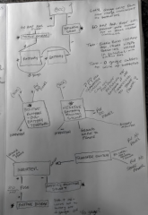
The plan is outlined in the attached photo.
We're still a little fuzzy on some of the wire sizes, but will re-read our manuals (fingers crossed)
One big thing is this: Once connected, we will not be plugging into shore power again for about a year. So with that, could we wait on upgrading the RVs existing converter/charger until then? It would be great to do that (and anything else that can wait) until then.

1605224467629.png1605224445316.png
 
Have you checked your post to see if YOU can read it clearly?
Thanks for pointing that out. I could read it, but I also know what it says. LOL
Is it possible to remove this thread? I could type this all out and then repost.
 
Last edited:
I think your fuse should be between the the positive bus bar and the battery. 60 amp fuse sounds a bit small. I use a 250 amp Class T fuse, but my battery bank is 560 Ah. For the price of those two Battleborn batteries you could build a DIY battery with twice the Ah, for almost half the cost.

Check the charge controller to see what the max awg wire it will allow. My Victron 100/50 charge controller specified a max 6 awg wire. Reality is that it could have been a smidge bigger, but I don't think 4 awg would have fit.
 
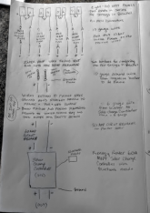
So I've spent this time typing up my plans and discovered I was missing a lot. I've spent many more hours reading back thru my manuals and other sources. I've updated wire and fuse sizes accordingly. I also realized that I still had some questions. I've typed questions directly in the PDF but will list them here too. My PDF also has details on the products that we've bought.

1) After reading both the solar charge controller and inverter manuals I'm unsure how to ground this system. See page 5

2) I'm unsure if it matters when connecting the batteries to the system which you connect first, positive or negative. My husband says it doesn't, but he also told be that we could connect this up without reading the manuals. LoL! He's a math man, not a handy man. ;)

3) Wire sizes. I've used the online wire calculators and load drop calculators and "think" I have these correct. In some areas you will notice that I put a wire gauge range in but did not choose one yet. That is because I am still unsure which size is best in that spot for my system design. Suggestions are welcomed.

4) We have another location option for the equipment that is slightly larger and closer to where the wires enter the roof. It is the other dinette bench that is just behind the RV axels. It's larger because it doesn't have a wheel well or any other factory installed wires & equipment in it. I'd like to use it but don't want to put too much weight behind the wheels. Page 4 has more info on this. Thoughts?

I'm handy and like to troubleshoot stuff and DIY but this kind of project is new to me. Our goal is to build the largest and most efficient solar system that we can afford. We've gone over budget already buying stuff that others told us to buy without first understanding what we were doing. That was a big mistake, 20/20 hindsight. We've returned things we could return. At this point, the larger components we have we own and need to make them work if possible. Thank you all for your insight, direction, and assistance. Smiles :)
 

Attachments

  • Full System Design.pdf
    811.2 KB · Views: 17
1) After reading both the solar charge controller and inverter manuals I'm unsure how to ground this system. See page 5

My approach was that I grounded those components that explicitly require grounding. The solar charge controllers, inverter and AC-DC converter. I did not run a lead from my negative bus bar to the ground bus bar. There is some discussion on this and I went with the "required" grounds.

The positive ground on the Renogy I have no idea on. Is that component made by Lucas (inside joke for British car fans)?

2) I'm unsure if it matters when connecting the batteries to the system which you connect first, positive or negative. My husband says it doesn't, but he also told be that we could connect this up without reading the manuals. LoL! He's a math man, not a handy man. ;)

I always connect negative last and disconnect negative first.

3) Wire sizes. I've used the online wire calculators and load drop calculators and "think" I have these correct. In some areas you will notice that I put a wire gauge range in but did not choose one yet. That is because I am still unsure which size is best in that spot for my system design. Suggestions are welcomed.

The couple that I saw looked OK. I ran 2/0 from my common bus bar to within about 3' of the trailer's main AC and DC distribution panel. Then from there I ran 6 gauge for the final 3'. My distribution panel has connections for two wires, not much larger than 6 gauge (the 2/0 would NEVER fit). I ran out of 6 gauge so I ran only one wire for each pos/neg leg. Once I resupply on 6 gauge I'll do the second wire. It's overkill as the OEM install at the factory used one wire.

8 gauge PV wire isn't all that common. 10 gauge is more common and that's what I used. If you use standard MC4 connectors, they may not work with 8 gauge PV wire. Your mileage may vary.

My approach was to put the biggest cable in that the component allowed. When a component called for or allowed something smaller and I had that cable I went with that. I limited my initial install to 10 gauge PV, 6 gauge welding, 2/0 gauge welding. I subsequently added 1 gauge because I didn't like how the existing inverter wires ended up.

I used a 250 amp Class T fuse downstream of the battery. This was based on recommendations found here. It's very expensive, but I wanted the best protection at that location. Your battery cable sizes will depend on distance, voltage and how many amps you think will go down the cable. The battery Ah isn't what dictates the cable size. I went with 2/0 based on distance, voltage and amps. My system is very compact, cable runs are short.

I don't see a disconnect switch between the battery and the fuse. Highly recommended.

A set of common bus bars makes wiring a lot easier. You can put only so many ring terminals/lugs on a post. I see the bus bars on page 1 but not page 2.

You can directly wire the batteries together, but you don't have to. 4/0 is likely overkill. I chose to keep the batteries distinct. They "connect" only at the fuse and the shunt.

I did not use any wire nuts in my system. Everything uses crimped on ring terminal or crimped on butt connectors. I'm a little anal about it though.

4) We have another location option for the equipment that is slightly larger and closer to where the wires enter the roof. It is the other dinette bench that is just behind the RV axels. It's larger because it doesn't have a wheel well or any other factory installed wires & equipment in it. I'd like to use it but don't want to put too much weight behind the wheels. Page 4 has more info on this. Thoughts?

My experience is that the more room you have to work with, the easier the install. Big cables bend only so much. A large area allows for a cleaner install at the expense of more cable. A cramped location can result in dropped tools.

It's good that you're considering the impact on weight. You're probably removing the batteries from the tongue so that right there is a big change. Do you know what your tongue weight is now? 10% to 15% is the target for good handling. Anything less than 10% is a problem. Maybe you can travel with a larger amount of water in the fresh water tank? Add a toolbox on the tongue?

I'm handy and like to troubleshoot stuff and DIY but this kind of project is new to me. Our goal is to build the largest and most efficient solar system that we can afford. We've gone over budget already buying stuff that others told us to buy without first understanding what we were doing. That was a big mistake, 20/20 hindsight. We've returned things we could return. At this point, the larger components we have we own and need to make them work if possible. Thank you all for your insight, direction, and assistance.

I blew my budget by almost 30%. A good amount of that was tools so I'm less concerned about that part of it. I'll be using those tools on the "next" RV, as well as other projects I'm sure. I bought a few things by mistake and had to buy the right things. The biggest logistics issues I had were cable lugs (ring terminals) and heat shrink tubing. Either I didn't have enough lugs for the stud size or I didn't have enough lugs for the cable size. Heat shrink tubing was on backorder. I did the install without it. Now that I have it, I need to take things apart to retrofit the heat shrink tubing on.

The converter is going to be a problem. If you were to buy an inverter/charger combo, that would solve the problem in a single component. If you buy the Windy Nation inverter then you'll need the separate converter and the transfer switch. Some inverter/charger units eliminate the need for the transfer switch, but that's an expensive option. If you tap power for the converter before the shore power hits the transfer switch then that solves the problem of having the converter on when it shouldn't be.
 
My approach was that I grounded those components that explicitly require grounding.
That makes sense. How the Renogy is grounded is determined based on whether or not you have a postive or negative grounded system. Any idea how I find out which I have?

If you use standard MC4 connectors, they may not work with 8 gauge PV wire.
The MC4 connectors are wired with 10 gauge. The 8 guage (which I already own) is coming off the busbar that combines the 10 gauge wires together. I think I'm good here.
I like the idea of using the largest size wire the component will accept. I own the 10, 8, and 6 guage wire already, but I can do this where I need to buy new wires & cables.
We tossed the idea of a busbar before the positive side of the battery because our batteries came with long bolts. I do see the appeal though.
I don't see a disconnect switch between the battery and the fuse. Highly recommended.
Like a circuit breaker? What is the benefit?

As tongue weight goes, we can juggle some things around if we need to add more up front. We have been considering using the double battery box that is on the tongue for some of our tools or putting a bike rack there. So you think that being right behind the axels vs over the axels will affect the weight distribution that much? The dinette bench farther back has a 40lb kayak and bulk food stored in it now. We figured the weight would not be a whole lot more than it is already, maybe 20-30lbs more? The wire running around the back wall will add a little weight though.

The converter is going to be a problem. If you were to buy an inverter/charger combo, that would solve the problem in a single component. If you buy the Windy Nation inverter then you'll need the separate converter and the transfer switch. Some inverter/charger units eliminate the need for the transfer switch, but that's an expensive option. If you tap power for the converter before the shore power hits the transfer switch then that solves the problem of having the converter on when it shouldn't be.

I'm not following you on this. We already own the Windy Nation Inverter and cannot return it. We are able to upgrade the existing converter. Are you saying that we need an additional separate converter just for our inverter in addition to the upgrade?
 
That makes sense. How the Renogy is grounded is determined based on whether or not you have a postive or negative grounded system. Any idea how I find out which I have?

Not really. I assume that you have a negative ground system. Allowing for a positive ground system is odd, as long as you discount those British cars.

Like a circuit breaker? What is the benefit?

Not a circuit breaker. Your fuse is your over current protection. The switch is there to allow you to turn everything off so you can perform maintenance without disconnecting cables.

As tongue weight goes, we can juggle some things around if we need to add more up front. We have been considering using the double battery box that is on the tongue for some of our tools or putting a bike rack there. So you think that being right behind the axels vs over the axels will affect the weight distribution that much? The dinette bench farther back has a 40lb kayak and bulk food stored in it now. We figured the weight would not be a whole lot more than it is already, maybe 20-30lbs more? The wire running around the back wall will add a little weight though.

The best way to tell is to get the trailer weighed on a CAT Scale at a truck stop. It's easy to do and not expensive. Download the CAT Scale app and that makes it easier. Proper tongue weight isn't one of those things you want to find out about 30 miles into a trip. I have a tongue scale that I use whenever there is a question. I'm a tool geek so I acquire stuff like that. If you were in the Denver area I would let you borrow it.

I'm not following you on this. We already own the Windy Nation Inverter and cannot return it. We are able to upgrade the existing converter. Are you saying that we need an additional separate converter just for our inverter in addition to the upgrade?

No, the new converter will be enough. I was offering an alternate solution, not realizing you had already bought the inverter.

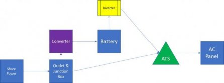
I posted a similar picture in a couple other threads. It may help to explain what I'm suggesting.

In the picture below, by wiring the converter into the shore power circuit before it hits the transfer switch you avoid all problems with the converter coming on when the inverter is running off of the battery. With this design, the converter has power only when shore power is connected.

In a normal RV without an inverter or generator, the converter is wired into the AC panel, which would mean that the converter gets power only when shore power is connected. In your situation, you cannot have the converter downstream of the inverter. If you did then the converter would be trying to charge the batteries while the inverter is drawing from the batteries. That's a really bad loop.
Converter Bypass Diagram No Generator.jpg
 
Back
Top