


You are using an out of date browser. It may not display this or other websites correctly.
You should upgrade or use an alternative browser.
You should upgrade or use an alternative browser.
Post a picture of your vehicle MPPT wiring?
- Thread starter LTLking
- Start date
justinm001
Solar Addict
- Joined
- Dec 18, 2022
- Messages
- 1,568
I can't follow the wiring on that.Here's part of mine
I edited the post.
Looking for wiring MPPT to bus, and other bus, load, inverter, battery.
justinm001
Solar Addict
- Joined
- Dec 18, 2022
- Messages
- 1,568
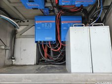
Up on ceiling is mppt (left) to Lynx shunt/distributor where everything connects toI can't follow the wiring on that.
I edited the post.
Looking for wiring MPPT to bus, and other bus, load, inverter, battery.
^Up on ceiling is mppt (left) to Lynx shunt/distributor where everything connects to
Up on ceiling is mppt (left) to Lynx shunt/distributor where everything connects to
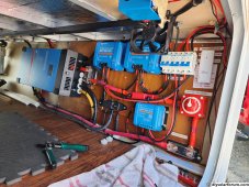
^Here’s what I have so far.
mikefitz
Solar Wizard
- Joined
- May 28, 2020
- Messages
- 2,983
MPPT positive line

mikefitz
Solar Wizard
- Joined
- May 28, 2020
- Messages
- 2,983
Don't use the low cost breaker shown, they are unreliable.Where’s the fuses, bus bars and what else is missing
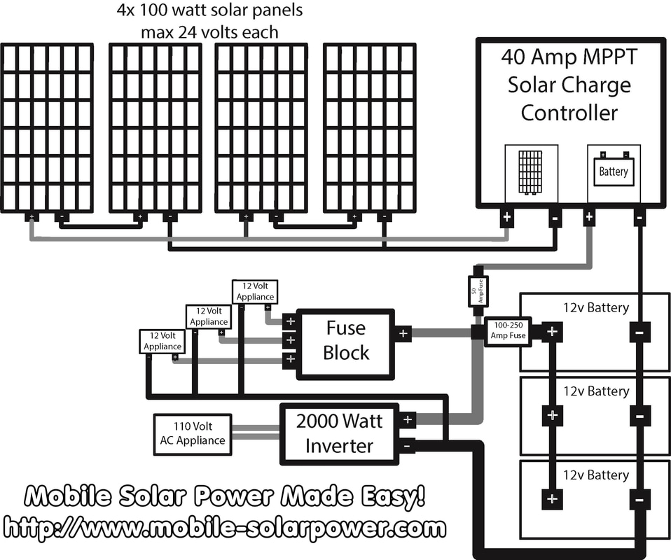
I posted a schematic diagram, follow that.
Before you do anything else, disconnect the negative wire at the battery. Reconnect this last, when the rest of the DC circuit is complete. This will prevent accedental shorts whilst working on the system. If at any stage you wish to make alterations , isolate the solar then battery. Reconnect battery first then solar.
Putting a circuit together is not following pictures, you need understand the resion for each wire and component part and how there are connected.
Follow my diagram and let's consider the battery.
The battery positive connects to the positive buss bar via a 'master' battery fuse and optional isolator. The battery negative (disconnected for now) connects to the negative buss bar. If the optional shunt (for battery monitor) is used connect as shown
Now the inverter, its 2000 watts, 12v. The inverter negative connects to the negative buss bar, the inverter positive connectes to the inverter fuse, then via a very short cable to the positive buss bar.
The MPPT battery negative connection connects to the negative buss bar, the positive connects via a fuse and a very short cable to the bositive buss bar.
The distribution fuse box common negative end is connected to the negative buss bar, the positive to the positive buss bar, again via a fuse.
Consider fuse values and types.
MPPT fuse, as its a 60 amp unit, use a 70 or 80 amp , midi link fuse with holder
Auxiliary fuse box, typically you wont need more the 50A for DC accessories, use a 50 amp Midi fuse with holder.
Inverter fuse, 200 watts at nominal 12v is 170 amps , use a 200 or 225 watt fuse, ANL or Mega with holder.
Master battery fuse, the maximum current will be in the region of 250 amps or lower if the battery has a BMS. Use a 250 amp
MRBF fuse in a Blue sea holder, bolts on the battery post.
Once all this is connected up , check carefully the wiring matches the schematic diagram.
Now energise the circuit by connecting the negative wite to the battery post. ( and turning on the battery isolator if fitted.)
At this stage the Inverter and 12v ancillaries should work, and the MPPT should show signs of life.
Now consider the solar. Connect the panel string to the MPPT an isolation switch in series with the positive.
Cables have not been considered. Estimate the maxinum current and select the the cable from this chart.
Part 1: Choosing the Correct Wire Size for a DC Circuit - Blue Sea Systems
Engineering high quality marine electrical components for safety, reliability and performance
 www.bluesea.com
Any questions?
Mike
Last edited:
You posted a diagram without fuses and bus bars.Don't use the low cost breaker shown, they are unreliable.
I posted a schematic diagram, follow that.
Before you do anything else, disconnect the negative wire at the battery. Reconnect this last, when the rest of the DC circuit is complete. This will prevent accedental shorts whilst working on the system. If at any stage you wish to make alterations , isolate the solar then battery. Reconnect battery first then solar.
Putting a circuit together is not following pictures, you need understand the resion for each wire and component part and how there are connected.
Follow my diagram and let's consider the battery.
The battery positive connects to the positive buss bar via a 'master' battery fuse and optional isolator. The battery negative (disconnected for now) connects to the negative buss bar. If the optional shunt (for battery monitor) is used connect as shown
Now the inverter, its 2000 watts, 12v. The inverter negative connects to the negative buss bar, the inverter positive connectes to the inverter fuse, then via a very short cable to the positive buss bar.
The MPPT battery negative connection connects to the negative buss bar, the positive connects via a fuse and a very short cable to the bositive buss bar.
The distribution fuse box common negative end is connected to the negative buss bar, the positive to the positive buss bar, again via a fuse.
Consider fuse values and types.
MPPT fuse, as its a 60 amp unit, use a 70 or 80 amp , midi link fuse with holder
Auxiliary fuse box, typically you wont need more the 50A for DC accessories, use a 50 amp Midi fuse with holder.
Inverter fuse, 200 watts at nominal 12v is 170 amps , use a 200 or 225 watt fuse, ANL or Mega with holder.
Master battery fuse, the maximum current will be in the region of 250 amps or lower if the battery has a BMS. Use a 250 amp
MRBF fuse in a Blue sea holder, bolts on the battery post.
Once all this is connected up , check carefully the wiring matches the schematic diagram.
Now energise the circuit by connecting the negative wite to the battery post. ( and turning on the battery isolator if fitted.)
At this stage the Inverter and 12v ancillaries should work, and the MPPT should show signs of life.
Now consider the solar. Connect the panel string to the MPPT an isolation switch in series with the positive.
Cables have not been considered. Estimate the maxinum current and select the the cable from this chart.
Part 1: Choosing the Correct Wire Size for a DC Circuit - Blue Sea Systems
Engineering high quality marine electrical components for safety, reliability and performance
Any questions?
Mike
Where’s the actual pictures of peoples actual setup showing where all the connections are?
Not victron. I can find those anywhere.
I still have connections in my setup I don’t know where they go.

justinm001
Solar Addict
- Joined
- Dec 18, 2022
- Messages
- 1,568
Don't use the low cost breaker shown, they are unreliable.
Which breaker do you recommend?
MisterSandals
Participation Medalist
Lots of diagrams and videos on the sister-site:
RV Solar Power Blue Prints
Building a vehicle mounted solar power system? Let me help.
www.mobile-solarpower.com
mikefitz
Solar Wizard
- Joined
- May 28, 2020
- Messages
- 2,983
breaker do you recommend
Use a fuse, its a lower volt drop alternative. If a breaker is a must then Blue Sea/ Bussmann.
Example,
I want to see what yours looks like.Lots of diagrams and videos on the sister-site:
RV Solar Power Blue Prints
Building a vehicle mounted solar power system? Let me help.www.mobile-solarpower.com
MisterSandals
Participation Medalist
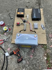
Ok here is a pic as currently running:

204Ah 2P4S
JBD 100A BMS
2A Heltec balancer (I have no idea what it does, if anything)
Victron 100/30
330W solar (165W x 2 in series)
Busman breaker (pictured) to 600W inverter
Solar cutoff in lower left.
Connected to pre-lithium PD-4645 converter. Rarely have shore power so 95%+ solar charged and maintained.
Similar threads
- Replies
- 24
- Views
- 500
- Replies
- 3
- Views
- 327
- Replies
- 21
- Views
- 927