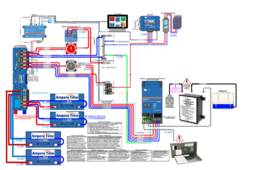
Currently building a large 12v system on the roof of a 33ft Class A Winnebago currently at 30a. Since I have no design experience, I paid to have it designed by a well-regarded source (Autarky Expedition Vehicles) but have had to make some changes, namely omitting two parallel Orion alternator DC-DC chargers and substituting JITA batteries for AmpereTime.
Here's the plan as it currently stands--it's about half built and I want to take this opportunity to make any corrections needed before I get further into it:

Panels: two sets of 3 series/2 parallel NewPowa 200W panels
Batteries: 4 300a JITA LiFePO4
Panel string fuses: one per 3-panel string in BougeRV fuse holders
MPPTS: two Victron SmartSolar 150/85s
MPPT breaker boxes: DIHOOL 30A: https://www.amazon.com/gp/product/B0BLGWV5JJ/
MPPT positive busbar breakers: Red Wolf 100a each, https://www.amazon.com/gp/product/B08ZSDYSBJ/
MPPT to distributor and distributor to 12v load center switches: YMIKO https://www.amazon.com/gp/product/B0BCKLTRH8
Inverter: Multiplus II 12v 3000vA 2x120v
Lynx Power In 1000a
Lynx Shunt 1000a
Lynx Distributor 1000a
Cerbo GX
GX Touch 50
Smart Battery Protect 220
I have some questions out to the designer, but in the meantime I wanted to put this out there for some advice.
- Breakers should be installed on the 6/3 wire from the ATS to the inverter and from the inverter to the 120V load center. What breakers are best for this? I can't find much on wiring breakers into 120v 6/3 Romex for some reason.
- What gauge should the distributor ground be, and should it be wired directly to the chassis? Is there anywhere else on the system that a chassis ground should be wired?
- The MPPTs have case ground screws as well. Should those be wired to chassis, and if so what gauge?
- Is there any harm in wiring the MPPTs to each other and the Cerbo using VE.Bus with terminators and generic RJ45 rather than buying extra long VE.Direct cables?
- What's the best order to energize it in to avoid damage? The batteries are fully charged already.
Thanks for looking at this, it's about $11k in parts and I'm trying to avoid smoking it with my very limited experience.
Here's the plan as it currently stands--it's about half built and I want to take this opportunity to make any corrections needed before I get further into it:

Panels: two sets of 3 series/2 parallel NewPowa 200W panels
Batteries: 4 300a JITA LiFePO4
Panel string fuses: one per 3-panel string in BougeRV fuse holders
MPPTS: two Victron SmartSolar 150/85s
MPPT breaker boxes: DIHOOL 30A: https://www.amazon.com/gp/product/B0BLGWV5JJ/
MPPT positive busbar breakers: Red Wolf 100a each, https://www.amazon.com/gp/product/B08ZSDYSBJ/
MPPT to distributor and distributor to 12v load center switches: YMIKO https://www.amazon.com/gp/product/B0BCKLTRH8
Inverter: Multiplus II 12v 3000vA 2x120v
Lynx Power In 1000a
Lynx Shunt 1000a
Lynx Distributor 1000a
Cerbo GX
GX Touch 50
Smart Battery Protect 220
I have some questions out to the designer, but in the meantime I wanted to put this out there for some advice.
- Breakers should be installed on the 6/3 wire from the ATS to the inverter and from the inverter to the 120V load center. What breakers are best for this? I can't find much on wiring breakers into 120v 6/3 Romex for some reason.
- What gauge should the distributor ground be, and should it be wired directly to the chassis? Is there anywhere else on the system that a chassis ground should be wired?
- The MPPTs have case ground screws as well. Should those be wired to chassis, and if so what gauge?
- Is there any harm in wiring the MPPTs to each other and the Cerbo using VE.Bus with terminators and generic RJ45 rather than buying extra long VE.Direct cables?
- What's the best order to energize it in to avoid damage? The batteries are fully charged already.
Thanks for looking at this, it's about $11k in parts and I'm trying to avoid smoking it with my very limited experience.


