diy solar

diy solar

Power draw

Joined
Aug 12, 2023
Messages
21
Location
California
Hello all,

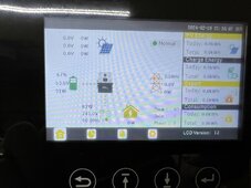
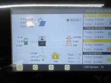
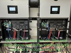
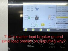
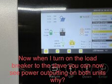
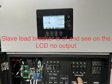
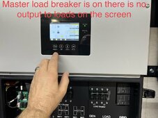
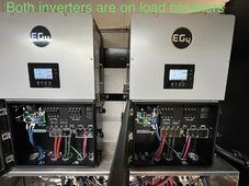
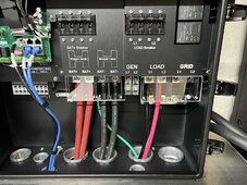
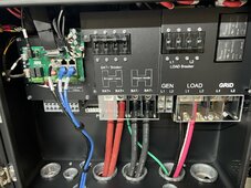
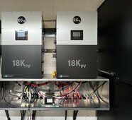
I have 2 EG4-18KPV Inverters with batteries connected and loads from the inverter connected to one PDB and it’s funny I see all works good but when I turn on the line breakers in the inverters I see a draw on the LCD screen but if I turn one of the breakers off no draw any ideas to why all settings are set to run off grid no ac input or PV input yet just batteries.
 
but if I turn one of the breakers off no draw

If they are running in parallel, if you turn off the Master, then the Slave doesn't know what to do.

Conjecture: if both are still on, and one looses connection to load (turn off breaker), then both might fail off because the master is commanding power from the slave, but the power is not reaching the load.

why all settings are set to run off grid no ac input or PV input yet just batteries.
Please restate your question. If you don't have grid or pv, it has to run off batteries.
 
I have have double checked all the torque settings on both EG4-18 KPV’s All communication cables are working as they should. My issue is if both inverters are powered on with the load breakers on and I have no loads connected. Both the inverters are just connected to the POWER DISTRIBUTION BLOCK. I am seeing watts coming from the batteries to the loads I do not have any loose connections it shows batteries going to the inverter and then down to the loads on this inverters .
Why?
If I just turn one load breaker on say the master, I am seeing 240 V 120 V from each line if I turn that one off and turn the slave load breaker on AC 240 V 120 on each line now I turn the master back on I still see 120 V per leg and 240 V with both units powered on but I am also seeing a draw from the battery to that power distribution block with no load connected as you can see in my photos, any help would be greatly appreciated
 

Attachments

  • IMG_3336.jpeg
    IMG_3336.jpeg
    204 KB · Views: 7
  • IMG_3334.jpeg
    IMG_3334.jpeg
    249.2 KB · Views: 7
  • IMG_3330.jpeg
    IMG_3330.jpeg
    320.9 KB · Views: 8
  • IMG_3329.jpeg
    IMG_3329.jpeg
    219.2 KB · Views: 8
  • IMG_3327.jpeg
    IMG_3327.jpeg
    239.6 KB · Views: 8
  • IMG_3326.jpeg
    IMG_3326.jpeg
    224.5 KB · Views: 8
  • IMG_3325.jpeg
    IMG_3325.jpeg
    210 KB · Views: 8
  • IMG_3307.jpeg
    IMG_3307.jpeg
    282.8 KB · Views: 8
  • IMG_3321.jpeg
    IMG_3321.jpeg
    294.5 KB · Views: 5
  • IMG_3332.jpeg
    IMG_3332.jpeg
    283.9 KB · Views: 5
  • IMG_3328.jpeg
    IMG_3328.jpeg
    311.7 KB · Views: 5
  • IMG_3324.jpeg
    IMG_3324.jpeg
    309.9 KB · Views: 5
  • IMG_3322.jpeg
    IMG_3322.jpeg
    265.6 KB · Views: 5
  • IMG_3311.jpeg
    IMG_3311.jpeg
    280.7 KB · Views: 5
  • IMG_3305.jpeg
    IMG_3305.jpeg
    198.6 KB · Views: 7
So if it’s not out putting any loads I’m seeing like 120 to 124 wants it fluctuates so when both load breakers are on both inverters I should see this wattage coming from the batteries or should it be zero watch coming being, so there’s no load connected
 
So if it’s not out putting any loads I’m seeing like 120 to 124 wants it fluctuates so when both load breakers are on both inverters I should see this wattage coming from the batteries or should it be zero watch coming being, so there’s no load connected
I also thought in standby mode. I should only see a idle consumption of like 18 wants per inverter that would be a total of 36 watts
 
So if it’s not out putting any loads I’m seeing like 120 to 124 wants it fluctuates so when both load breakers are on both inverters I should see this wattage coming from the batteries or should it be zero watch coming being, so there’s no load connected
It has to account for the power being consumed by the inverter. It appears to treat that as Load. Otherwise you would see watts from battery, and 0 to load.
 
I also thought in standby mode. I should only see a idle consumption of like 18 wants per inverter that would be a total of 36 watts
You may have to enable stand-by mode. Most homes have some draw 24/7. Clocks or any electronics waiting for a command (TV, microwave, internet, etc). So it doesn't even try.
 
It has to account for the power being consumed by the inverter. It appears to treat that as Load. Otherwise you would see watts from battery, and 0 to load.
So 107 watts from the master and about 82 watts from the slave is that considered idle consumption or is that because the load breakers are turned on and things are energize, even though it is not out putting any loads?
 
You may have to enable stand-by mode. Most homes have some draw 24/7. Clocks or any electronics waiting for a command (TV, microwave, internet, etc). So it doesn't even try.
Not sure if you seen this photo, but these inverters are not connected to any loads except for the power distribution block. I have not ran my wire from that power distribution block to my sub panel for my loads so that’s why I’m wondering why I see the watts coming from the battery when the load breakers are on, and there is no loads present if I turn one load breaker on on the inverter master I see no watts coming from it if I turn the slave inverter on, I will see watts from that inverter as well as the master if I turn the master load breaker off, and the slave Load breaker is on I see no loads but when they were both on I see watts coming maybe I am being stupid and not comprehending this, but it seems to me that there shouldn’t be any watts showing. Where are the watts going and what is putting a load on it?
 

Attachments

  • IMG_3321.jpeg
    IMG_3321.jpeg
    294.5 KB · Views: 3
2 times 70 watts (140) is the max I would expect with no load.
Understood so if I’m seeing 107 watts on the master inverter and about 98 to 100 Watts on the slave inverter are those numbers combined or is that reading basically off of the master inverter as a combination?
 
Hmmm... put clamp meter on the load wires. See if they are really passing power.

Someone who has 2 18kpv in parallel will have to answer what is on the screens.

Maybe to load breakers also control the inverter. If the load breaker is off, it also turns off the ac output of the inverter.
 
Last edited:
First photo is master inverter connected to load L1 second photo load L2 Third photo slave inverter for photo L2 fifth photo, master positive DC cables master negative DC cables slave positive DC cables slave negative DC cables it looks like it is reading in milliamps on AC and DC lines
 

Attachments

  • image.jpg
    image.jpg
    112.6 KB · Views: 5
  • image.jpg
    image.jpg
    111.4 KB · Views: 5
  • image.jpg
    image.jpg
    123.1 KB · Views: 4
  • image.jpg
    image.jpg
    120.5 KB · Views: 4
  • image.jpg
    image.jpg
    117.8 KB · Views: 4
  • image.jpg
    image.jpg
    127.1 KB · Views: 4
  • image.jpg
    image.jpg
    133.2 KB · Views: 3
  • image.jpg
    image.jpg
    113.9 KB · Views: 6
Hmmm... put clamp meter on the load wires. See if they are really passing power.

Someone who has 2 18kpv in parallel will have to answer what is on the screens.

Maybe to load breakers also control the inverter. If the load breaker is off, it also turns off the ac output of the inverter.
I really appreciate your help Rich I am very new to this Forum and I do not even know where to post this type of question any help on your side would be great. Thank you so much for all your help.
 
Do you think I have any issue with the inverters the way I see it on the LCD screens.
Do you think it is operating correctly? I do not see any errors or anything. I just see the draw and was not for sure why
 
Back
Top