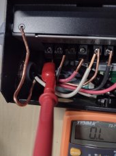
The unit does not bond N-G.
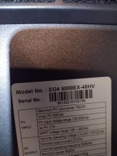
Build date is correct for shipped without bonding screw.
It won't make a bond.
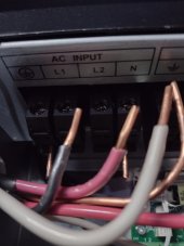
There is some discussion the 6000EX has an isolation transformer internally. One aspect is that if this is true, if you ever want to bypass the inverter entirely for repairs or maintenance, you will need a 3 pole transfer switch with a neutral in order to supply neutral to your subpanel on grid power. On this unit, the input N is not tied to the output N due to the isolation transformer. Common neutral can't be used due to the isolation transformer.
If you had the 6500EX (late model with latest firmware or earlier model with bonding screws removed and latest firmware), it would be more suited for your UPS scenario. If you want an automatic transfer switch, it should have neutral switching so you can supply grid neutral. That requires a 3 pole. Also, when it comes to bonding N-G, you will need to have N-G bonded in the subpanel. This creates a problem on grid backup power, you will have 2 N-G bonds in the system. You will need to have some type of dynamic switching for N-G bond in the subanel.
None of this is really required to some extent as the 6000EX has an isolation transformer. As long as it has power on the 2 hots coming in, it will create the N on output, just like the transformer from the utility grid. That is why N-G bonding is done at the subpanel. You should not need a transfer switch unless you want the ability to bypass the inverter entirely.


")