diy solar

diy solar

MPP LV6548 Ground/Neutral Safety?

Yea, your right. I totally understand now, and yes it was a definition issue. Thanks. This all does seem to be more complicated when running the AC input, bypass, and powering sub from main. I understand the benefits though.
With the older electrical system I have, I'll be doing a lot of testing prior to any installation to see what needs to be fixed, I'm sure there are things. I think originally, there weren't even any grounded outlet plugs in this house.
There are many shortcomings of the NEC, terminology is one of them. With the advent now of off grid solar inverters that can automatically revert back to grid and the associated N-G bonding issues, the NEC definitely has fallen behind.
 
I have given this a lot of thought maybe too much to the point of deliriousness. So with that in mind. If we cannot remove the path of objectionable current would it not be safer to wire it as recommended in the manual so that the chance of one connection failure will not cause a more dangerous condition. The objectionable current I have found in my system has never been in the field. It seems to be limited only to conductors between the panels and the inverters. Clearly it would be best to eliminate it but at this point I'm not sure that is possible with units working in parallel.
 
I have given this a lot of thought maybe too much to the point of deliriousness. So with that in mind. If we cannot remove the path of objectionable current would it not be safer to wire it as recommended in the manual so that the chance of one connection failure will not cause a more dangerous condition. The objectionable current I have found in my system has never been in the field. It seems to be limited only to conductors between the panels and the inverters. Clearly it would be best to eliminate it but at this point I'm not sure that is possible with units working in parallel.
Have you tried the new firmware? I guess it does not have a non-bonding option. MPP seems to support removing the bonding screw. Is that an option for you?
 
Have you tried the new firmware? I guess it does not have a non-bonding option. MPP seems to support removing the bonding screw. Is that an option for you?
I have not updated my firmware yet. I couldn't find the cable to connect my laptop to the units. There is one at my friends home where we are installing a second build, just took it out of the box last week. I am going to work there this weekend so I should be able to get one soon. Hoping to do the update to see if this solves the issues. I would like to not go into the units.
 
I have given this a lot of thought maybe too much to the point of deliriousness. So with that in mind. If we cannot remove the path of objectionable current would it not be safer to wire it as recommended in the manual so that the chance of one connection failure will not cause a more dangerous condition. The objectionable current I have found in my system has never been in the field. It seems to be limited only to conductors between the panels and the inverters. Clearly it would be best to eliminate it but at this point I'm not sure that is possible with units working in parallel.
I think we may all be delirious.

If you (and by "you" I mean it generically) leave the objectionable current in place, and you touch a conductive area on the case of one inverter with one hand and any other grounded metal with the other hand, some current will flow through your body because you will be another parallel neutral current path, but it will probably not be enough to feel. This will happen under normal circumstances.

A real danger will be from the following scenario and others like it.

The neutral connection between the top inverter and the transfer switch is not solid. Maybe you didn't tighten a screw as much as you should have. Maybe you tightened it too much and stripped it. Maybe you didn't tighten it at all. Maybe you used a neutral wire that was too small to safely carry the current. The neutral connector slips out of the connector or the connection heats up enough to char the neutral wire and breaks the connection. It is even possible that you were careless and didn't even connect a neutral wire between the top inverter and the transfer switch.

Now all of the top inverter's neutral current is traveling through the EGCs that connect the two inverters, but you installed EGCs that were smaller than the neutral wire. One of the EGC's connections heats up enough to char the wire and break the connection. Now some of your 120V circuits and all of your 240V circuits do not work.

You go down to the basement or to the garage barefoot. The top inverter is still on so you use the display or maybe take the wiring cover off. If you touch a conductive area of the inverter case, your body is now the path for all of the top inverter's neutral current through your bare feet and the damp concrete floor. Is that enough to kill you? Maybe.

What if you touch a conductive part of the top inverter case with one hand and any other grounded metal (bottom inverter, panel, transfer switch, water or gas pipe, etc) with the other hand or the opposite arm or leg? Is that enough to kill you? Quite possibly.

I know you think things like this would never happen but in one of Mike Holt's videos he talks about the service wires in his main panel that were put into the lugs by the electricians that wired his house but the lugs were not tightened at all. The wires were just loose in the lugs.

1647107205302.png

Here are some videos from post 71. They are worth watching.


This one is also very interesting if you have time to watch the entire video.

 
Just want to share what I am currently doing. I do not plan to use bypass:
  • Updated LV6548 firmware so voltage is not present between ground and neutral.
  • Keep grounds and neutrals separate in panel. Connect a true Earth ground to ground bus if I feel the need to.
  • Use a separate, high efficiency 48V battery charger. This charger can be turned on with a wifi outlet switch if I want to setup scheduled charging. My system has enough solar so that this charger will never be used, but it's nice to have this option.
Not ideal, but it's safe and gets the job done. No need to modify the units, so beginner friendly.
That's a good way to isolate the system from the grid. And still use the grid power, when needed.
 
Just want to share what I am currently doing. I do not plan to use bypass:
  • Updated LV6548 firmware so voltage is not present between ground and neutral.

Current, not voltage will run between the 2 inverters on both the neutral and ground. There shouldn't be voltage, the neutral and ground are bonded together at each end. If you did have voltage, then either bonding of N-G is not present or you have resistance in a connection.

  • Keep grounds and neutrals separate in panel. Connect a true Earth ground to ground bus if I feel the need to.

Ground and neutral will be bonded together inside each inverter under inverter power.

  • Use a separate, high efficiency 48V battery charger. This charger can be turned on with a wifi outlet switch if I want to setup scheduled charging. My system has enough solar so that this charger will never be used, but it's nice to have this option.
Not ideal, but it's safe and gets the job done. No need to modify the units, so beginner friendly.
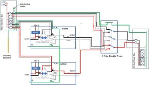
It isn't grid power that is an issue if a 3 pole double throw is used and neutral is switched. There will be objectionable current between both inverters on the EGC due to both inverters having N-G bond under inverter power. The battery charger isn't needed, the charger in the inverters will work fine and safely.

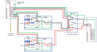
The conversation is all about the N-G bond on each inverter under inverter power and the resulting objectionable current that will occur on the EGC between both inverters due to the parallel path with neutral. My approach is to manage the current without removal of the EGC on the inverters and keep the length as short as possible. I consider the 2 inverters as one 240V split phase generator and the objectionable current is confined between the 2 inverters. The EGC between the 2 would be less than 2 feet. There is no other way around this unless either neutral for each inverter is kept isolated from the other neutral, this would require 2 subpanels, one dedicated with it's neutral to it's corresponding inverter. This is impractical and unnecessary. Second option would be to not have the EGC on either inverter. I consider that unsafe. A short to case in the inverter could turn the case hot. Next option is removal of the ground screw for the N-G inside the inverter. I consider this unsafe also.

This is my solution. It is the best option after many threads of discussion. The only objectionable current would be between the 2 inverters when under inverter power.


Daisy chain #2.jpg
 
Just to be clear, using a battery charger from grid and keeping the inverters offgrid is the simple way, I was explaining earlier in the thread and exactly how I'll be running my system. Of course I originally saw this on wills video for his tesla syetem using the driveway panels. Super simple, a lot less wiring, switches, and boxes.
That being said....if you do not install the way Zwy is intending as pictured in his diagram, you will not be utilizing the functionality of any of these units...while maintaining the grid ability at the same time. Zwy setup really does showcase the maximum versatility in all cases.
 
Last edited:
It really comes down to how you want to use your system. Once you figure that out, then you have to figure out how to make it work easily and safely.
 
Just to be clear, using a battery charger from grid and keeping the inverters offgrid is the simple way, I was explaining earlier in the thread and exactly how I'll be running my system. Of course I originally saw this on wills video for his tesla syetem using the driveway panels. Super simple, a lot less wiring, switches, and boxes.

Using a battery charger doesn't change anything, doesn't matter if these units are run off grid or setup for bypass. The current on the EGC will always be there when the inverter is providing power and there is an imbalance between legs.

Any inverter that bonds N-G at the inverter and runs with a pair or more of units will have current on the EGC between the units, the current will be same amps as on the neutral.

That being said....if you do not install the way Zwy is intending as pictured in his diagram, you will not be utilizing the functionality of any of these units...while maintaining the grid ability at the same time. Zwy setup really does showcase the maximum versatility in all cases.
It sure rolled around in my mind for days. At first I thought the phasing would prevent any current on the ESG or traveling thru one inverter to the other on neutral. But after some members tested this, it became apparent that current is following a parallel path on neutral and EGC between the inverters.

I will be installing a white wire instead of a green wire between the two inverters for the EGC. This would identify it could carry 1/2 of the neutral current. Probably print a label also indicating as such at each end. From the master inverter to main panel it will be a green wire.
 
I have it in writing from MPP solar stating the neutral ground bond is only active when inverting from solar/battery. When bypassing power from the grid, it will disconnect the neutral/ground bond
I asked watts247 and he said there is a firmware update that fixed the issue, not sure how that all works but sounds good I guess
 
I asked watts247 and he said there is a firmware update that fixed the issue, not sure how that all works but sounds good I guess
Sounds good but that was known before. The problem is under inverter power when N-G are bonded on both inverters. This is where current from the neutral is shared due to the parallel path on the EGC.

Grid power bypass is not a problem, there isn't any bonding taking place in the inverter.

Many people don't quite understand why or what this is about concerning the current on the EGC between units under inverter power. That is a problem.
 
Current, not voltage will run between the 2 inverters on both the neutral and ground. There shouldn't be voltage, the neutral and ground are bonded together at each end. If you did have voltage, then either bonding of N-G is not present or you have resistance in a connection.


Ground and neutral will be bonded together inside each inverter under inverter power.


It isn't grid power that is an issue if a 3 pole double throw is used and neutral is switched. There will be objectionable current between both inverters on the EGC due to both inverters having N-G bond under inverter power. The battery charger isn't needed, the charger in the inverters will work fine and safely.

The conversation is all about the N-G bond on each inverter under inverter power and the resulting objectionable current that will occur on the EGC between both inverters due to the parallel path with neutral. My approach is to manage the current without removal of the EGC on the inverters and keep the length as short as possible. I consider the 2 inverters as one 240V split phase generator and the objectionable current is confined between the 2 inverters. The EGC between the 2 would be less than 2 feet. There is no other way around this unless either neutral for each inverter is kept isolated from the other neutral, this would require 2 subpanels, one dedicated with it's neutral to it's corresponding inverter. This is impractical and unnecessary. Second option would be to not have the EGC on either inverter. I consider that unsafe. A short to case in the inverter could turn the case hot. Next option is removal of the ground screw for the N-G inside the inverter. I consider this unsafe also.

This is my solution. It is the best option after many threads of discussion. The only objectionable current would be between the 2 inverters when under inverter power.


View attachment 87093
Yeah, I am pretty sure everyone here knows that voltage will not "run" as you described. If there is a difference in potential across a conductor, then current will flow. This is basic electricity. Before firmware update, there was 12VAC between ground and neutral. Not sure why, I did not look into the firmware and did not inspect the actual circuit. Your diagram does not help us understand why there was voltage with the old firmware. Once firmware update was complete, 0V was present. Do you know the difference in the firmware?

As I said in past posts, can someone email MPP and find out what they updated? I do not care about the changes, but if you do, you need to get this information and see what changed.

Yes, I think that was clear from the beginning. We all understand that the bond will be present. Because I do not have any ac input (like I said in my post), it is fine to leave it. The output for split phase configuration is in series. So having those bonds is fine. If the output were in parallel, then perhaps I would reconsider.

No, I would not consider them a 240V "generator". It has two separate sources that are connected in series.

How much current are we talking here? How much have you measured? There are a lot of posts in this thread, so I missed the point about current on ground. There should be zero or nearly zero. They should all be connected to a reference potential, and if there is no current measured, it should be fine.

I see the frustration you guys have in this situation if you also connect the ac input. Really depends on how you wire it. There are multiple safe configurations I can think of. Imagine if some inverters are in series, and some are in parallel to increase 120V capacity, then you connect multiple inverters ac inputs? Again, need to think about it and wire it how you see fit.
 
Sounds good but that was known before. The problem is under inverter power when N-G are bonded on both inverters. This is where current from the neutral is shared due to the parallel path on the EGC.

Grid power bypass is not a problem, there isn't any bonding taking place in the inverter.

Many people don't quite understand why or what this is about concerning the current on the EGC between units under inverter power. That is a problem.
So if using two inverters to run two phase is where the problem still exists? Running one unit has all issues fixed?
 
Using a battery charger doesn't change anything, doesn't matter if these units are run off grid or setup for bypass. The current on the EGC will always be there when the inverter is providing power and there is an imbalance between legs.

Any inverter that bonds N-G at the inverter and runs with a pair or more of units will have current on the EGC between the units, the current will be same amps as on the neutral.


It sure rolled around in my mind for days. At first I thought the phasing would prevent any current on the ESG or traveling thru one inverter to the other on neutral. But after some members tested this, it became apparent that current is following a parallel path on neutral and EGC between the inverters.

I will be installing a white wire instead of a green wire between the two inverters for the EGC. This would identify it could carry 1/2 of the neutral current. Probably print a label also indicating as such at each end. From the master inverter to main panel it will be a green wire.
Yes, using a battery charger does remove the issues when connecting to a true earth ground through one inverter ac input. That is why I am doing it. That is why it is so easy to use. Think about all the various configurations where using the ac input or multiple ac inputs could be problematic.

Yes, then don't do that. It really depends on how you wire it. If you wire it for 240V with communication cables, then the output is in series. If you put them in parallel to increase 120V output capacity, then you should wire it another way.

It really depends on what configuration one chooses to use. You could have three phase with three units, and a 4th unit only doing 120V. Which ac input would you use? It also depends on how you wish to ground the system. There are many variations here.
 
Sounds good but that was known before. The problem is under inverter power when N-G are bonded on both inverters. This is where current from the neutral is shared due to the parallel path on the EGC.

Grid power bypass is not a problem, there isn't any bonding taking place in the inverter.

Many people don't quite understand why or what this is about concerning the current on the EGC between units under inverter power. That is a problem.
How much current is flowing between the units on ground? I see there being an issue when the outputs are in parallel, but not so much when they are in series. Perhaps keeping them separate would avoid that current flow, but I still want a non-current carrying reference potential across the whole system. And some form of true earth ground, or electron sink.
 
Yeah, I am pretty sure everyone here knows that voltage will not "run" as you described. If there is a difference in potential across a conductor, then current will flow. This is basic electricity. Before firmware update, there was 12VAC between ground and neutral. Not sure why, I did not look into the firmware and did not inspect the actual circuit. Your diagram does not help us understand why there was voltage with the old firmware. Once firmware update was complete, 0V was present. Do you know the difference in the firmware?

I don't, I was hoping you had more "pull" to get the information on the firmware. I do believe some units were shipped where under grid power, the unit was inadvertently bonding N-G according to some reports. This might be the fix if that had occurred.

As I said in past posts, can someone email MPP and find out what they updated? I do not care about the changes, but if you do, you need to get this information and see what changed.

Yes, I think that was clear from the beginning. We all understand that the bond will be present. Because I do not have any ac input (like I said in my post), it is fine to leave it. The output for split phase configuration is in series. So having those bonds is fine. If the output were in parallel, then perhaps I would reconsider.

The problem I see is where members are running neutral and an EGC to the subpanel fed by the inverters. This makes the EGC hot the entire length from the subpanel to the inverters. And considering the N-G bond at the main panel, in addition to having an EGC on the input side per inverter, the whole thing becomes a giant ground loop with objectionable current possible in many directions.

No, I would not consider them a 240V "generator". It has two separate sources that are connected in series.

I'll disagree..........

How much current are we talking here? How much have you measured? There are a lot of posts in this thread, so I missed the point about current on ground. There should be zero or nearly zero. They should all be connected to a reference potential, and if there is no current measured, it should be fine.

The current will be 1/2 of the neutral current imbalance. If there were 30A imbalance, then 15A. For subpanels that are not balanced well, a system could potentially see 1/2 of the inverter max output of 54A, possibly more under surge conditions, up to 54A. This should not be occurring.

I see the frustration you guys have in this situation if you also connect the ac input.

That is not an issue if neutral is switched. I think you are missing the point. There will be current on the EGC between the 2 inverters when an current is flowing on neutral due to imbalance of phases.

Really depends on how you wire it. There are multiple safe configurations I can think of.

Sure, show one. We can all pick it apart, Filter Guy surely will find something..........

Imagine if some inverters are in series, and some are in parallel to increase 120V capacity, then you connect multiple inverters ac inputs? Again, need to think about it and wire it how you see fit.
The imbalance load could increase considerably with unit in parallel such as 4 inverters.
 
Back
Top