diy solar

diy solar

PV voltage drops ~60% when connected to charge controller (Victron 100|50)

But when I tilt the panel to match the sun I get a much more respectable 5A.
So with 1 panel actually facing the sun, are volts ~22Voc (~18Vmp.), and amps ~5A?

This is enough for your charge controller to work with a 12V battery.

18Vmp x 5A = 90W

If your charge controller is not seeing this, then check the connections.
 
So with 1 panel actually facing the sun, are volts ~22Voc (~18Vmp.), and amps ~5A?

This is enough for your charge controller to work with a 12V battery.

18Vmp x 5A = 90W

If your charge controller is not seeing this, then check the connections.
Thx MisterSandals, I'm still trying to figure this out. I've ruled out the panels themselves as the cause of my problem.

Today I observed 12.78V difference between the PV input wires, with panels *detached* via breaker. PV wires are only connected to my combiner box with breaker and fuses, and the charge controller itself. Connections are secure. Battery sits at 13.4V.

Do you happen to know: under which circumstances could my charge controller be providing a voltage to the panels via the input wires? Is this indication of a fault or is this a feature intended to provide some "boost" to the panels? Nothing in the manual about it, and preliminary googling did not reveal an answer. Thank you in advance, again :cool:
 
Today I observed 12.78V difference between the PV input wires, with panels *detached* via breaker.
Between which wires?

PV wires are only connected to my combiner box with breaker and fuses, and the charge controller itself.
Can you post a pic?

There seems to be a lot going on between whatever your array consists of and the SCC.
How about taking 1 panel and connecting it directly to the SCC? Connect the battery first of course.
 
Between which wires?


Can you post a pic?

There seems to be a lot going on between whatever your array consists of and the SCC.
How about taking 1 panel and connecting it directly to the SCC? Connect the battery first of course.
Sure. I am sorry that I am not skilled at explaining these concepts in words, I am open to any change of phrasing or terminology you might suggest.

imgur dot com/a/9TkunAa The photos in this link are with zero panels connected to the combiner box.

I can connect a panel directly to the SCC, but I'm still overly cautious about this backfed power - is there any risk of hurting the PV cells?
 
Ok so the PV input to the SCC shows "some voltage". This has to be leaked thru from the battery but to what extent. I tried to reach mine but its a bit hurried in the RV and I did not want to mess with any disassembly.

Can you check the amps at the PV input on the SCC? With array disconnected of course. Its probably just negligible bleed thru.
I can connect a panel directly to the SCC, but I'm still overly cautious about this backfed power - is there any risk of hurting the PV cells?
If the amps from your measurement above are low (less than 1), you can give it a go with a panel to see if somehow your combiner box or connectors are problematic.
 
Ok so the PV input to the SCC shows "some voltage". This has to be leaked thru from the battery but to what extent. I tried to reach mine but its a bit hurried in the RV and I did not want to mess with any disassembly.

Can you check the amps at the PV input on the SCC? With array disconnected of course. Its probably just negligible bleed thru.

If the amps from your measurement above are low (less than 1), you can give it a go with a panel to see if somehow your combiner box or connectors are problematic.
Thank you for checking out the photos. Won't testing amps at the PV input on the SCC result in a spark / short circuit through my multimeter?

If the PV terminals have 12V battery power available to them then what is the difference between
1. touching multimeter probes to the PV terminals
2. touching red and black wires while they are connected to the PV terminals, shorting the circuit with a spark

My current understanding of current is that V=IR, and I=V/R. The current drawn by a load is a factor of the voltage input and physical resistance of the components used in the load circuit. But my understanding of current is clearly not complete because I am very hesitant to perform the test you asked me to perform. My instinct is that testing amperage at this point will result in a short circuit. Do you have any suggested reference other than Victron "Wiring Unlimited"?
 
I went ahead and did it anyway, using the fused 200mA test option, and the measurement exceeded 200mA. If I'm doing something obviously wrong in this test, or misunderstanding you, please let me know.
 
I was hoping someone following along would test theirs. Lets see if one of the experts @sunshine_eggo can help.

Hey sunshine_eggo. sallaben is trying to debug some odd charging issues. He noticed that with a Victron 100/50 or similar, connected to only a battery, that there is voltage at the PV input terminals. Normal?
I definitely recall reading 0.00, 0.01V PV input voltage when only connected to battery back on Monday when I first made this post.

There was a firmware update for the device today. That's the only thing I've changed. Hope eggo can chime in!
 
You updated thru the app? Does everything look normal on the app settings and readout values?

This is good new info to have, maybe you've discovered a nasty bug in the firmware?
yep, updated through the app with no warnings or error codes.

App readout looks identical to the way it did on Monday, except for PV voltage. Bluetooth connection is fine and I'm on firmware version 1.61 now. I'll try resetting to default settings and reconfiguring the charger. edit: reset made no difference

Here is the v1.61 changelog entry:
  • Improve battery voltage auto-detect corner cases, by completely eliminating the chance of a charger running with an auto-detect pending after the next restart or power cycle. Three changes: (1) in case the charger can’t detect the battery voltage, because no battery voltage is present at power-up on the battery terminals, select 12V. (2) after doing a restore settings to default, perform an auto-detect after 10 seconds. The 10 seconds is to allow a distributor to power down the product in order to leave the product as if its fresh from the factory. (3) Models without load-output would do an auto-detect only if there is PV present. This is changed: auto-detect happens always within 10 seconds after power-up, unconditionally and same for all models.
  • SmartSolar Control display: no longer show the battery voltage setting on the display at first power-up, to simplify the process and interaction with auto-detect. The setting is still available in the settings menu.
 
I was hoping someone following along would test theirs. Lets see if one of the experts @sunshine_eggo can help.

Hey sunshine_eggo. sallaben is trying to debug some odd charging issues. He noticed that with a Victron 100/50 or similar, connected to only a battery, that there is voltage at the PV input terminals. Normal?

I'm not on site, so I can't test; however, I have seen this behavior on 2X Outback FM80 MPPT my neighbor has. Array completely disconnected from the MPPT, but there's still a PV voltage.

Additionally, this week has the dubious distinction having presented the worse ever solar collection from my array... 0.2kWh from a 3kW array. Cold, overcast with intermittent snow and downright miserable.

Part of the reason for so little collection was the battery is unheated, and I'm being very conservative with my management. It has to be over 8°C before it will charge. Between 3° and 8°, no charging is allowed, but PV can power loads. Below 3°C, the MPPT is completely shut off.

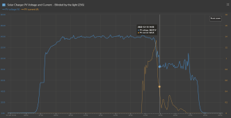
Plot of PV voltage and current:

1671168533665.png

Even with horrific conditions and only a 0.5A pull from the panel, Vmp still stayed above 80V. Typical Vmp is around 105-110V.

I would expect the 100/50 to behave in a similar manner scaling for voltage.
 
Sorry, I didn't understand what you were asking until now. I think that is the culprit rather than the charge controller. I read an astounding 0.05A from the panel itself when I read Isc with the multimeter. But when I tilt the panel to match the sun I get a much more respectable 5A.

I didn't expect a flat-laying panel to produce effectively 0 amps - it's turned into a mostly clear day with plenty of direct sun. Does this mean, crappy panels? Or is this true of most mono panels?
Sallaben, I appear to have the exact same problem. If you are still interested, it may help to check out my thread at: https://diysolarforum.com/threads/m...put-full-voltage-current-until-10-30am.52428/
 
Not 100% sure on that SCC, but usually direct to battery SCC get their power from PV to run the SCC.

It sounds like the SCC is stuck in PWM mode and does not go to MPPT mode.

The SCC will do this if it cannot definitively find an MPPT point which involves seeing a drop off in power as it lightens load on panels.

One reason why this might happen is if input PV Vmp is not high enough above battery voltage. With two series panels that would not be the case.

Other rare reason is PV illumination is so low it collapses PV voltage with SCC overhead power to run the SCC. Since SCC only takes a few watts to run, this is rare. Running in PWM mode takes less overhead power than MPPT mode.

Two things I can think of to check. One is PV Isc, short circuit current. It appears your meter can do 5A. Likely have to move leads to 5A current ports. In the 5 amp measurement mode, just put the leads across the panel with breakers open to SCC. You might overscale the 5A but should not blow the meter's protection fuse which is likely 10A.

Second is measure panel's Voc while you turn on breaker. If SCC starts an MPPT search, as soon as you close breaker to PV panels, the panels voltage should drop by about half its unloaded Voc value then quickly ramp up in voltage. If SCC immediately jumps to battery voltage it means the controller is jumping directly to PWM mode.

Other dumb mistake is make sure your battery needs charging and the SCC is set up for proper float voltage, absorb voltage, and bulk current so SCC does not think battery is fully charged therefore PV power is not needed.
 
Last edited:
Back
Top