diy solar

diy solar

Questions about fuses for inverter and converter

I make the ac map to be...
Please fill in the gaps

Code:
main                30
air conditioner        20
refridgerator        15
?                    15
gfi_outlet            15
converter            15
microwave            15

There is a 15 amp breaker labeled "refer/gen". That's what your "?" referred to. Only 6 breakers, not 7. I'm don't know what "refer/gen" stands for.
 
There is a 15 amp breaker labeled "refer/gen". That's what your "?" referred to. Only 6 breakers, not 7. I'm don't know what "refer/gen" stands for.
There are six breakers and six labels.
So gen may be generator.
But that would be pretty bad form if its backfeeding through branch breaker#3 without an interlock.
 
My mistake 6 breakers including main
refer/gen is one label.
The fridge is dual ac/dc and probably propane also.
No clue what refer/gen would mean.
 
There are six breakers and six labels.
So gen may be generator.
But that would be pretty bad form if its backfeeding through branch breaker#3 without an interlock.
I don't think "gen" is referring to generator, unless it's referring to an electrical starter for the generator, and I would seriously doubt that that starter would be 120v. That'd be illogical.

I opened the wall, and this is what I found:

IMG_20210415_170901.jpg
 
We are all waiting with baited breath to see what is in the box that the orange wires go into.
The orange stuff is 10awg romex, confirm?
 
We are all waiting with baited breath to see what is in the box that the orange wires go into.
The orange stuff is 10awg romex, confirm?
The orange wire has the following label along the jacket: "Encore Wire Corp 10/2 W/G Type NM-B (UL)".

It's not easy to open this box since the screws are on the opposite side and there's only a few inches of clearance. Even a stubby screwdriver wouldn't fit.

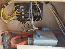
I did run that snake camera inside a hole in the side, and found this:

PHO00022.JPG
 
The orange wire has the following label along the jacket: "Encore Wire Corp 10/2 W/G Type NM-B (UL)".

It's not easy to open this box since the screws are on the opposite side and there's only a few inches of clearance. Even a stubby screwdriver wouldn't fit.

I did run that snake camera inside a hole in the side, and found this:

View attachment 45271
That looks like a transfer switch.
There should be 3 wires.
One for shore power.
One for the generator.
And one to the main breaker in the ac distribution panel.
 
That looks like a transfer switch.
There should be 3 wires.
One for shore power.
One for the generator.
And one to the main breaker in the ac distribution panel.

Yes, the shore and mystery box cable go in, and an orange cable goes to the power center breaker panel.

If it is a transfer switch, does that mean that it will automatically connect shore or mystery box inlet to Main, whichever is supplying 120v power?
 
Yes, the shore and mystery box cable go in, and an orange cable goes to the power center breaker panel.

If it is a transfer switch, does that mean that it will automatically connect shore or mystery box inlet to Main, whichever is supplying 120v power?
That is how its supposed to work.
Both hot and neutral should be switched.
That means your alternate power source has to have its neutral and ground bonded.
 
With what we have seen so far.
The legacy electrical does not give me a warm and fuzzy feeling.
 
@smoothJoey @Whinny

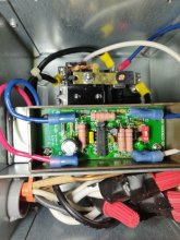
I managed to open up the metal box behind the wall, and this is what I found:

IMG_20210417_171941.jpg

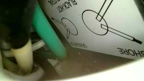
Definitely looks like an automatic transfer switch. I think the underside of the lid gives it away:

IMG_20210417_172040.jpg

I guess I still don't know for sure that it's all been wired up. I mean, it'd be pretty lame if they wired the inlet into this ATS, but then capped it off inside without actually wiring it. The wires are really densely packed, so it's hard to see, and I am nervous to mess around in there, because even though shore is disconnected, who knows how long this thing holds energy?

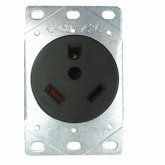
My last question for now is, supposing that this inlet is all wired up correctly with the ATS, can I install a common 30 amp RV receptacle (Nema TT-30R) into that inlet box, and then fashion a 30 amp cable to the inverter and have that plugged into the inlet receptacle? Would that work?

Here's what that kind of receptacle looks like:

6957064521078.jpg
 
@smoothJoey @Whinny

I managed to open up the metal box behind the wall, and this is what I found:

View attachment 45544

Definitely looks like an automatic transfer switch. I think the underside of the lid gives it away:

View attachment 45545

I guess I still don't know for sure that it's all been wired up. I mean, it'd be pretty lame if they wired the inlet into this ATS, but then capped it off inside without actually wiring it. The wires are really densely packed, so it's hard to see, and I am nervous to mess around in there, because even though shore is disconnected, who knows how long this thing holds energy?

My last question for now is, supposing that this inlet is all wired up correctly with the ATS, can I install a common 30 amp RV receptacle (Nema TT-30R) into that inlet box, and then fashion a 30 amp cable to the inverter and have that plugged into the inlet receptacle? Would that work?

Here's what that kind of receptacle looks like:

View attachment 45546
That is an outlet not an inlet.

There should be no caps to hold power.
Get yourself a chicken stick.
 
I suggest that you bond the neutral/ground on your generator and on your inverter.
Does your RV have an inlet?
If yes you can use or for shore power or the generator.
And wire the generator leg of the transfer switch to your inverter.
And the final bit its to wire your converter in parralel with the shore power side of the inverter.
Don't forget the breaker.
Is that clear?
 
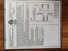
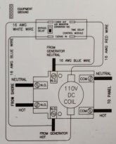
I can't see the picture or the diagram very well.
That is a double breaker that switches both hot and neutral, confirm?
 
On the diagram one of the inputs show should NO for normally open and one should say NC for normally closed.
Which input is which?
 
I cropped and rotated the diagram if that makes it easier to see:
That makes no sense.
One of them should be normally closed and the other should be normally open.
I am having a blonde day though.
 
The reason you couldn't get to the screws is because RV's are built from the inside out and it's easier for the assembly line. Makes for a right pain in ass for everybody else though...
For inverter use the switch is probably wired "backwards"-you dont want a battery holding the relay, you want shore power to do it....
 
If you want to do internal changes get yourself some Wago's or equivalent but don't buy them online too many knock offs
I would hard wire the inverter don't bother with any plugs..
 
@smoothJoey @Whinny

According to the installation manual (found here: https://wfcoelectronics.com/wp-content/uploads/2020/04/T-30-T-57R-Manual.pdf), it says that shore is "pass-through" and therefore always on. It also says something about some kind of protection against both sources of power being on at the same time.

Nothing about normally open or normally closed. It is a 20 to 30 second time delay though switching to generator. I don't understand the mechanics very well.

Here's the Amazon page if that helps: https://smile.amazon.com/dp/B008OJ7EIA/ref=cm_sw_r_cp_apa_glc_fabc_PYZGSP0YGE29AG446XCX

I was hoping this would be as easy as properly wiring the AC side of the inverter to that mystery box in the battery compartment, which I am assuming is an inlet.
 
Back
Top