diy solar

diy solar

Relays: NC vs NO or other solution?

MisterSandals

Participation Medalist
Joined
Nov 5, 2019
Messages
10,045
Location
Silicon Valley
I am hoping someone can help me find a solution. I am learning about relays and hoping to incorporate one to cut the power between my array and solar charge controller. 400w array, 45A SCC.

My "thought" was to use an NO (normally open) relay but wondering how i would power a "close" in the event of a BMS cutoff or other loss of battery power (goal: stop power to the SCC). With a power loss (or a BMS cutting power), it seems i cannot close the relay - doh!

So if I were to use an NC (normally closed) relay, I would need to power it "open" 24/7/365 using at least an amp of power. And I am guessing holding the switch open all the time, would shorten the life of the relay significantly.

Is there something other than a relay I should consider?
 
One possibility is a latching relay. There are 2 types, one alternates states...apply power and it turns on and stays on until power is applied again, then it turns off. A second type has 2 coils, one will turn it on, other coil turns it off.

 
Last edited:
A latching (AKA bi-stable) relay has two separate coils that need to be triggered by separate circuits. Let's say you have a NO latching relay that is currently in the open state. If you energize the "close" coil, then the relay closes, and remains closed even if you de-energize the close coil. Subsequent pulses into the close coil will have no effect. To open the relay, you need to energize the other coil, the "open" coil. The effect of de-energizing or sending additional pulses again has no state changing effect.

In a simple circuit with just your controller and your latching relay, if you want to effectively control a latching relay to open on one parameter level and close on another from the controller, it would need two separate and inversely dependent outputs for relay control. I have a Victron BMV which has a bi-stable DT relay and two output ports, one that energizes on NO, the other that energizes on NC. This instrument then is capable of supporting control using a latching relay. I'm planning to use it for primary control in the system I'm building.

--mark
 
I am hoping someone can help me find a solution. I am learning about relays and hoping to incorporate one to cut the power between my array and solar charge controller. 400w array, 45A SCC.

My "thought" was to use an NO (normally open) relay but wondering how i would power a "close" in the event of a BMS cutoff or other loss of battery power (goal: stop power to the SCC). With a power loss (or a BMS cutting power), it seems i cannot close the relay - doh!

So if I were to use an NC (normally closed) relay, I would need to power it "open" 24/7/365 using at least an amp of power. And I am guessing holding the switch open all the time, would shorten the life of the relay significantly.

Is there something other than a relay I should consider?
Funny you should ask. I'd like to use a temp sensor to trigger a cutoff in all circuits going to the inverter, which includes PV, battery and AC in. I mentioned the shunt based breakers to a friend, and the GFP breakers with a 1 amp breaker that trips the other breakers. A friend said, "why not a relay". After thinking about it, the problem with a relay is it doesn't have the protections of a breaker, such as an arc extinguisher.

So, the question I have for you is what is your use case? The downside of a breaker solution is it would require a manual reset, which isn't ideal if you are looking for full on/off automation.

Note, I'm no expert in this. I'm learning, and largely doing this so I can learn and create new things like innovation in safety. You just happened to touch on what I've been thinking a lot about.... relays vs breakers with low amp trip.

If we can find breakers that can likewise be triggered to reset, then you can effectively have the function of a relay with the protection of a breaker.

This doesn't answer your question completely. But at least it gives you something other than a relay to consider. :)

Looking forward to hearing your thoughts on relays vs breakers.

Here is an example of a GFP breaker.
 
Last edited:
if you want to effectively control a latching relay to open on one parameter level and close on another from the controller, it would need two separate and inversely dependent outputs for relay control.
Thanks for the explanation, I am trying to get my head around how to put it to use.

How does this sound:
Manual push button to energize the NO (connect array to the SCC). I like the idea of being in control of when this gets turned on.

To energize the NC (disconnect array from SCC for various reasons) I am struggling where to get the power when the BMS hits any fault condition.

I have a Victron BMV which has a bi-stable DT relay and two output ports, one that energizes on NO, the other that energizes on NC. This instrument then is capable of supporting control using a latching relay. I'm planning to use it for primary control in the system I'm building.

This looks like the way to go. Are you using the BMV-702 or BMV-712?
Looks like it is intended for use with Victron SCC and BMS for a pretty tight system - is that what you are doing?
Do you happen to have a schematic or link to a similar setup (especially how it controls the latching relay)?
 
I'm new to solar, but have been doing electronics for years. Most relays are available as both NO & NC together. They are often called form C relays. A single pole would have 3 pins, a normally open, a common, and a normally closed. You simply wire in on the terminals that work for your application. The nice thing about this is that you can select what happens if you lose power.

I work in the security industry and we use relays to open and close door locks. Some doors should fail secure - locked. Other doors should fail safe - unlocked. You want people to be able to use the fire exits even when power is out, but having the safe door open when power goes off is just a bad movie trope.
 
Can you guys link to some of these cool relays? I'd like to bookmark and come back when I need them. I know link to specific relays won't likely meet our specifications in use; but it will help to begin the search when you have real descriptions and specs.
 
So, the question I have for you is what is your use case?
My use case is to disconnect 400 watts of panels from a my SCC (Morningstar MPPT 45) in the event of low voltage cell, high voltage cell or low temperature to stop charging.
I cannot just disconnect battery from the SCC, its manual says irreperable damage will occur if battery disconnected while energized array connected.

The downside of a breaker solution is it would require a manual reset, which isn't ideal if you are looking for full on/off automation.
My thoughts on breakers? I like the idea a LOT, especially the robustness of a breaker. I actually also like the idea of a manual reset: I'd REALLY like to know what is going on if the BMS says to shut down and get that worked out before manually resetting.

Happen to have a drawing or link to how one would implement this?
 
Happen to have a drawing or link to how one would implement this?

Only theory for me currently. No drawing. In my use case, I don't plan to fire from BMS, but as you know some BMS can use a relay. A relay could, in turn, fire a breaker. Might even be able to skip the relay, IDK. Would have to play with it, which is what I'd want to do before creating a diagram. See how easy it is to trip.

All I know in the description for the one I linked says it trips on 1 amp. Idea is it detects ground being used. But, don't see why you can't trip that with 1 amp from any source. I haven't hunted around yet to see what other ones are out there, as I haven't spec'd out my PV circuit yet. If I use that in my initial PV circuit, it will be as a traditional ground trip. It will be some time before I add the smart features. In the meantime, having an idea what I want to build, I'm collecting everything I can that can help me build it. So, just in R&D phase right now for "smart" tripping circuits.

Regarding the PV circuit, my panels arrive next week. So, I'll be under more pressure to complete the initial "non-smart" PV circuit design, that may just have GFP.
 
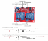
KNACRO DC 12V 2-Channel Self-Latching Relay Module One-Button Bistable Switch One-Button Start Stop 30 amp each 60 in parallel $14.80

How would this be wired up (array, SCC, BMS...)? I attached the pic for quick reference.

1) Power Supply +
2) Power Supply -
3) 1 Channel High Level External Trigger (Left)
4) 1 Channel High Level External Trigger (Right)
5) K1 1-Channel NO
6) G1 1-Channel COM
7) K2 2-Channel NO
8) G2 2-Channel COM
 

Attachments

  • KNACRO DC 12V.png
    KNACRO DC 12V.png
    334 KB · Views: 24
Getting on Dia now, it'll take a bit though.
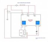
Basically tie the 2 High Level triggers together and use a momentary switch to supply the High Level trigger.
Parallel the relay outputs to achieve the 60 amp rating & battery voltage to the + & - terminals.
If you only require 30 amps then an indicator LED Red = 1 Green = 0 could be fed by the other relay. Add a second single relay board if you need 60 and indication.
 
Is there a good reason to need to disconnect the PV at a low battery voltage?


So if I were to use an NC (normally closed) relay, I would need to power it "open" 24/7/365 using at least an amp of power. And I am guessing holding the switch open all the time, would shorten the life of the relay significantly.

I think you have NC and NO confused.
 
Is there a good reason to need to disconnect the PV at a low battery voltage?

There are going to be more, not less, reasons as we go down this path of a synchronous disconnect of current sources with various events fired. I suspect this is going to become best practice, and definitely falls under better safe than sorry. I have other reasons than the OP; but I like that he's tying this to a BMS disconnect. This is a circuit design we need in our chest of safety options.

I think you have NC and NO confused.

The takeaway is that he'd have to maintain 1 amp current to maintain one of the two states, thus the discussion of Latching Relays and Breakers. In those solutions, a pulse can open the PV circuit instead of a continuous 1 amp. We may not know why the BMS triggered a disconnect until we investigate. But, we definitely do not want an unnecessary continuous draw from the battery when it does, especially if it does it for a low voltage or low temp cutoff.

To go further than @MisterSandals, I plan to implement something similar, only it would be fired by Arduino/PI, which could, among many sensors and inputs, receive state from the BMS. There is a very high probability I'll incorporate his design for the same reasons, preventing unnecessary load in states requiring investigation or intervention while cutting off current from various sources.
 
Last edited:
Here you go:
Excellent! I actually understand it except for the S1 High Level Trigger.

It must trigger both the connect and disconnect states in the latching relay?
Since I am counting on a BMS cutoff conditions to initiate the disconnection process,
how would that work? I get the impression it should be a pulse.

Sorry, this is all new to me.
 
Is there a good reason to need to disconnect the PV at a low battery voltage?
No, there is no need. The BMS cutoff does not indicate the particular condition (high/low/temp). In fact, it may require some intervention to restart charging after low battery voltage disconnect.

I think you have NC and NO confused.
Good because it bothered me the way i (mistakenly) understood it!
 
Excellent! I actually understand it except for the S1 High Level Trigger.

It must trigger both the connect and disconnect states in the latching relay?
Since I am counting on a BMS cutoff conditions to initiate the disconnection process,
how would that work? I get the impression it should be a pulse.

Sorry, this is all new to me.
Correct it would be a pulse to both open the PV circuit and to connect it. If you are using the BMS state as a Hi = conduct or Lo = open the circuit the transition needs to create a pulse for each transition as the Hi/Lo state would not flip it (Hi>Lo) once it flopped it (LO>Hi).
I see an Ardurino and sketches in our future. LOL
 
Back
Top