diy solar

diy solar

Relays: NC vs NO or other solution?

@SCClockDr What's going on here?

View attachment 3086

And what are you drawing schematics with? I don't see your answer in this thread, although I loved your reply.
That is an LED indicator to be placed where the operator can observe whether the PV's are connected (ILLUMINATED) or off (DARK).
The PV voltage is way to variable to reliably power an LED.
 
Thanks for the explanation, I am trying to get my head around how to put it to use.

This looks like the way to go. Are you using the BMV-702 or BMV-712?
Looks like it is intended for use with Victron SCC and BMS for a pretty tight system - is that what you are doing?
Do you happen to have a schematic or link to a similar setup (especially how it controls the latching relay)?

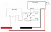
Here is a rough schematic on how I plan to set this up using a dual coil latching relay (SPST NO Type) and a BMV 712. My converter (Mean Well HRPG -600-15) has a remote control pinout on an exposed header. When the RC circuit is open, the unit makes DC output, and stops output when the RC circuit is shorted. THE BMV-712 can be programmed to change its internal relay state when voltage or SOC thresholds are crossed. So let's say I'm currently charging - the BMV is energizing the NO port with DC from the power bus, energizing the left coil on the relay. The RC circuit is open and the converter is making DC. When high SOC or voltage cutoff is reached, the BMV changes state and energizes the NC port, and when the right coil is energized, the the latching relay changes state and closes, shorting the RC circuit and idling the converter. The reverse will happen when low voltage or SOC occurs.


schematic.jpg
 
the BMV changes state and energizes the NC port, and when the right coil is energized, the the latching relay changes state and closes, shorting the RC circuit and idling the converter. The reverse will happen when low voltage or SOC occurs.
First THANKS for taking the time to make the schematic, these take time and effort!

Sorry if this is a basic question but why does this latching relay change state with an input being "energized" and the latching relay (KNACRO in SCClockDr's schematic) require a pulse?

Most solar systems and particularly the BMS's that I've seen work is my energizing or de-energizing. And in such systems, dumb parts like relays and switches can (should?) handle most connects and disconnects. I'd like to stay simple (dumb?) if at all possible.

I have to say, when I saw the comment about pulses and Arduino's, I was more than a little discouraged. And even looking down the road, selling an RV with electrical guts that look like a HeathKit might be sub-optimal: i'd certainly have reservations buying someone else's "tinkering project".
>>
...needs to create a pulse for each transition as the Hi/Lo state would not flip it (Hi>Lo) once it flopped it (LO>Hi).
I see an Ardurino and sketches in our future.
/>>

Sorry so many topics in here. Really wondering how to keep this with simple dumb parts (relays, switches) and NOT circuit boards and Arduinos.
 
First THANKS for taking the time to make the schematic, these take time and effort!

Sorry if this is a basic question but why does this latching relay change state with an input being "energized" and the latching relay (KNACRO in SCClockDr's schematic) require a pulse?

See this earlier post. A latching relay changes state when current is initially sent into the coil that opposes the current state of the relay - can be a pulse, many pulses, or continuous current.
 
UFF DA - looks like the BMV-712 will not fully support my use case. After studying the manual, it seems to be incorrectly engineered. The stated use case is using the internal relay to start a generator when the relay closes (NC is energized), but the response of the unit is only correct for half of the scenarios.

We can set these parameters: SOC floor, SOC reset, low voltage floor, low voltage reset, high voltage ceiling, high voltage reset, temp floor, and temp reset.

Assume NC energized = charging on, NO energized = charging off (this can be inverted but that applies to ALL settings)
--------------------------------------------------------------------
Battery SOC drops below SOC floor, NC is energized, charging
Battery SOC rises above SOC reset, NO is energized, no charging
Battery voltage falls below low voltage floor >10 s, NC is energized, charging
Battery voltage rises above low voltage reset, NO is energized, no charging
HOWEVER:
Battery voltage rises above high voltage ceiling, NC is energized, charging
Battery voltage falls below high voltage reset, NO is energized, charging
Temp falls below low temp floor, NC is energized, charging
Temp rises above low temp reset, NO is energized, no charging


Sigh - back to the drawing board. Why would I want to turn on a generator when battery voltage goes too high or temp goes too low? Victron got this one wrong.
 
I am hoping someone can help me find a solution. I am learning about relays and hoping to incorporate one to cut the power between my array and solar charge controller. 400w array, 45A SCC.
My "thought" was to use an NO (normally open) relay but wondering how i would power a "close" in the event of a BMS cutoff or other loss of battery power (goal: stop power to the SCC). With a power loss (or a BMS cutting power), it seems i cannot close the relay - doh!
So if I were to use an NC (normally closed) relay, I would need to power it "open" 24/7/365 using at least an amp of power. And I am guessing holding the switch open all the time, would shorten the life of the relay significantly.
Is there something other than a relay I should consider?
Some fundamentals: A relay is a switch that is toggled internally by a electromagnet coil pulling against a spring. Normally Open relays is the connection is open (power will not flow through) without any voltage being applied to the coil and the internal spring is holding it open. Normally Closed is the switch is closed (connection made) and the spring holds it closed without power applied to the coils.
A latching relay is one without a internal spring, it toggles open or closed and stays there (latches) until you hit the coil again with the opposite polarity and the switch moves again. There are MANY types of latching relays but swapping polarity at the coil is the most common type by a small margin. This is usually accomplished by an extra post on the relay.

You can turn any relay/contactor into a 'normally open' or a 'normally closed' by the addition of a inexpensive relay control board (which itself has a small relay on it) and connecting your relay coils to the NO or NC side of the board output. As the relay control board only uses milliwatts its more efficient to have that held in a state and use a big Normally Closed contactor that'll open for your trigger event. That way you're not holding open a large relay and burning watts continuously and wearing out the coils. However continuous duty relay coils are made for just that: Continuous duty, cheapo relays may say continuous duty but they're usually not. The trigger signal can be just a few milliwatts.
The downside here is that if you lose your trigger power to the coil its going to stay closed.

For example the temperature drops below freezing and you want to cut off charging from the panels: Your triggering signal goes to the control board trigger input which switches its own relay closed which then allows power to flow to the contactor coils which opens it up as long as the event trigger is applied. Since I assume you live in a area where it's not below freezing most of the year this'd be the most power efficient.

You don't have to worry about overvoltage because thats what charge controllers are FOR.

The same logic can be applied to almost any situation: You have a config that operates in a usual state but want to change it so you have to apply power to relays to open up the circuit.

Con is that when your control circuitry fails its going to fail with things energized. Sooner or later control circuitry always, ALWAYS fails.

IMO you should spend the money on getting good quality NO continuous duty relays and then hold them closed with your control circuitry. Good quality relays really only burn a few watts and do NOT get hot when energized. When something fails it just doesnt work things have failed in a DE-energized condition.

For now I'd recommend you stay away from solid state relays, they're not as intuitively obvious as you'd think and it'll just confuse you.
 
I am hoping someone can help me find a solution. I am learning about relays and hoping to incorporate one to cut the power between my array and solar charge controller. 400w array, 45A SCC.

My "thought" was to use an NO (normally open) relay but wondering how i would power a "close" in the event of a BMS cutoff or other loss of battery power (goal: stop power to the SCC). With a power loss (or a BMS cutting power), it seems i cannot close the relay - doh!

So if I were to use an NC (normally closed) relay, I would need to power it "open" 24/7/365 using at least an amp of power. And I am guessing holding the switch open all the time, would shorten the life of the relay significantly.

Is there something other than a relay I should consider?
i did the same thing on a portable bank i have to protect the scc in the event of bms failure and when the battery protect shuts down (set to 12.5v) i have to jumper the relay to start the charge cycle. maybe you could install a switch to control the jumper?
 
IMO you should spend the money on getting good quality NO continuous duty relays and then hold them closed with your control circuitry. Good quality relays really only burn a few watts and do NOT get hot when energized.

GREAT! How does this one look? I cannot tell how much power it consumes but worth a trial run for $35.

 
Last edited:
Back
Top