You are using an out of date browser. It may not display this or other websites correctly.
You should upgrade or use an alternative browser.
You should upgrade or use an alternative browser.
[RESOLVED] Unusual 2P4S staggered configuration
- Thread starter Rrrracer
- Start date
My 2p worth...
a) the changing colour of those wires confuses me.
b) I don't like seeing the wires so close to other terminals - where they could possibly rub - esp. as it doesn't look like a static environment to me.
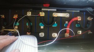
Technically if electrically wired as 2P4S with equal length wires, it will work. But it looks like you have two different types of cells in there as they have different terminal positions - is that intended?
wpns
Solar Joules are catch and release
Wow, with all those different colors that’s a disaster waiting to happen. I can’t even tell what cell terminals are positive, and you _know_ the next person to work on that is going to make a mistake.
Rrrracer
New Member
- Joined
- Aug 21, 2021
- Messages
- 18
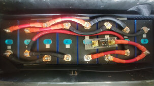
It came in a motorhome we purchased, I will be the next person to work on it and am trying to wrap my head around what's going on. Yes, there are two different cell types. I removed the BMS/negative/positive terminals but everything else is as it came.
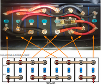
My question is if the way the cells are set up is valid? From what I can tell it is a 2p4s setup but the arrangement is unusual. Battery reads 13.28v from outermost negative terminal to outermost positive terminal. I made a quick diagram to clarify since the wiring is confusing as all get out:

My question is if the way the cells are set up is valid? From what I can tell it is a 2p4s setup but the arrangement is unusual. Battery reads 13.28v from outermost negative terminal to outermost positive terminal. I made a quick diagram to clarify since the wiring is confusing as all get out:

McKravitts
Solar Enthusiast
- Joined
- Sep 8, 2022
- Messages
- 571
The cell numbers are hidden on some of the cells. If we just label them 1 to 8 from left to right it is clear that 1 and 3 are in parallel, cells 2 and 4 are in parallel, cells 5 and 7 are in parallel and cell 6 and 8 are in parallel. That is 4 sets of 4 parallel combinations of 2 cells each.
1&3 Positive connects to 5&7 negative. 5&7 positive connects to 2&4 negative. 2&4 positive connects to 6&8 negative.
Take the positive off the fuse on 6&8 and the negative off the negative of 1 or 3 and you have a 2p4s configuration.
The wire length on the parallel combinations appear to be equal length which is good for cell balance but the series conections vary in length.
You might want to increase the current carrying capacity of the series connections if needed, otherwise I don't see any problem leaving the rest as is.
Last edited:
sunshine_eggo
Happy Breffast!
Someone deserves a throat punch.
robbob2112
Doing more research, mosty harmless
That is reducustupid - all those extra stacked lug conection points and that fuse - I would break it down and put it back together using bus bars.
Rrrracer
New Member
- Joined
- Aug 21, 2021
- Messages
- 18
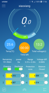
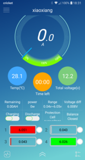
I started to dig into the bank because this is what I saw when I connected to the BMS (RadioB Tech 4s 120a, model RB-124S120A):

B- terminal connected to the bank reads 13.2x V, and the C- terminal coming out of the BMS is 12.8x V, so a discrepancy there as well.
I will probably just disassemble the pack and put it back together in the correct configuration with bus bars. I don't see a problem with the fuse but am happy to be corrected.
sunshine_eggo
Happy Breffast!
Location of sense cables is likely wrong.
meetyg
Solar Addict
- Joined
- Jun 4, 2021
- Messages
- 1,240
Oh my!I started to dig into the bank because this is what I saw when I connected to the BMS (RadioB Tech 4s 120a, model RB-124S120A):
View attachment 229612
I will probably just disassemble the pack and put it back together in the correct configuration with bus bars. I don't see a problem with the fuse but am happy to be corrected.
I hope this is a result of some erroneous readings by the BMS, and not the actual voltages!
wpns
Solar Joules are catch and release
Wait, so in addition to the weird wiring, one of the (parallel sets of) cells is at zero and two are at 5+ volts? #It'sDeadJimI started to dig into the bank because this is what I saw when I connected to the BMS (RadioB Tech 4s 120a, model RB-124S120A):
View attachment 229612
B- terminal connected to the bank reads 13.2x V, and the C- terminal coming out of the BMS is 12.8x V, so a discrepancy there as well.
I will probably just disassemble the pack and put it back together in the correct configuration with bus bars. I don't see a problem with the fuse but am happy to be corrected.
Yes, disassemble it, but see if there are any functional cells, and test them completely before rebuilding it into anything (and then throw them all out and start over).
Rrrracer
New Member
- Joined
- Aug 21, 2021
- Messages
- 18
I removed the cables, cells seem to check out OK if not very well balanced (in order from L to R in the pic):
1) 3.302v
2) 3.297
3) 3.302
4) 3.297
5) 3.300
6) 3.304
7) 3.300
8) 3.308
My next step is to take four similar cells, build a 4s battery and then reconnect the BMS to see if it is working properly.
1) 3.302v
2) 3.297
3) 3.302
4) 3.297
5) 3.300
6) 3.304
7) 3.300
8) 3.308
My next step is to take four similar cells, build a 4s battery and then reconnect the BMS to see if it is working properly.
Rrrracer
New Member
- Joined
- Aug 21, 2021
- Messages
- 18
The plot thickens.. I reworked the cells back to a 2P4S configuration with some bus bars I had laying around (not enough to do the whole thing, so I had to reuse some of the cables.) Hooked the BMS up and.... no dice, it freaks out again.
What am I missing? AFAIK, there is no setting to change in the BMS as it is still considering this a 4s setup, yes?
What am I missing? AFAIK, there is no setting to change in the BMS as it is still considering this a 4s setup, yes?


sunshine_eggo
Happy Breffast!
Cut off the ends of the BMS leads and put on new ones.
sunshine_eggo
Happy Breffast!
And what the eff? The two cells at the right end are different.
EDIT: DOH! the two at BOTH ends are different.
Now the interleaving thing kinda makes sense. Maybe they were trying to make each "cell" have one of each kind in it.
EDIT: DOH! the two at BOTH ends are different.
Now the interleaving thing kinda makes sense. Maybe they were trying to make each "cell" have one of each kind in it.
Rrrracer
New Member
- Joined
- Aug 21, 2021
- Messages
- 18
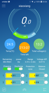
BOOM! Replacing the ring terminals on the BMS sense wires fixed the problem! We are in business LOL... everything working normally from what I can see.
Strange how it worked on the 4S setup but not on the 2P4S until the terminals were changed but hey, no complaints. The two battery styles were indeed paired with each other.
Thank you guys so much for the help. Now to see how they have all the solar hooked up...
Strange how it worked on the 4S setup but not on the 2P4S until the terminals were changed but hey, no complaints. The two battery styles were indeed paired with each other.
Thank you guys so much for the help. Now to see how they have all the solar hooked up...
GXMnow
Solar Wizard
- Joined
- Jul 17, 2020
- Messages
- 2,837
Yeah, I would certainly recommend paralleling one of each type cell for each position. So each cell group is then one wide post and one narrow post cell.DOH! the two at BOTH ends are different.
Yes please show us how they put panels rated 24v and 12v in series with a 36v parallel.Thank you guys so much for the help. Now to see how they have all the solar hooked up...
sunshine_eggo
Happy Breffast!
BOOM! Replacing the ring terminals on the BMS sense wires fixed the problem! We are in business LOL... everything working normally from what I can see.
Strange how it worked on the 4S setup but not on the 2P4S until the terminals were changed but hey, no complaints. The two battery styles were indeed paired with each other.
Thank you guys so much for the help. Now to see how they have all the solar hooked up...
When you see goofy assed cell readings that mathematically sum to something sensible, it's usually a bad BMS sense connection. Given that users typically install their own ring terminals, that's the first place to check.
Similar threads
- Replies
- 1
- Views
- 261
- Replies
- 14
- Views
- 548


