diy solar

diy solar

Ryobi Zero-Turn Mower SLA to LiFePo4 Conversion - (Updated - Build Complete With Pics!)

Same charger OP used or a different one?
If different, might have a bunch of caps his doesn't.
Maybe mower motor control has a bunch of caps.
Isolated from batteries and discharged, you could measure with a meter (if your DMM has capacitance range. But mine doesn't go high enough for my inverter.)
Or measure RC time constant with resistor and battery.

Could be you need a precharge circuit like the guys with lithium battery and inverter. In your case, since you have a plug, just SPST switch in series with a resistor across it.
It's a different charger. I can measure capacitance with my DMM, not sure the range.

Do you mean put a SPST switch across the leads to the charger to discharge any caps before I plug in the mower?
 
In series with wire between charger and connector.
With switch open, plug in connector. Instead of high inrush current and a spark, lower current flows through resistor, gradually charging capacitors to match battery voltage. Then close switch (it has to be able to carry charge current). Then turn on charger (or plug into AC.)

The switch won't be used to make or break under load, so it just needs to carry current while connected.

There are a number of battery-disconnect switches, some rated up to 48V. Their current handling would be overkill for charge current. They typically are rated 48V max (or less), not enough to cover actual charging voltage of a 48V battery. But I think the distinction is just human safety, not technical capability; above that voltage, terminals are supposed to be inaccessible. Since your current draw is less, the cheap knockoff switches are probably good enough (For inverter loads, Blue Sea and others have quality switches.)

DC circuit breakers like from Midnight should fit the bill too.
Ah, so like this using a 20A panel mount Midnight breaker? What size resistor?

breaker.png
 
If 20A is sufficient for the charge controller.
Normally we would only run 80%, 16A, through a 20A breaker. But I think Midnight said theirs are OK at 100% (because magnetic/hydraulic, not thermal/magnetic)

Unlike an inverter, your system won't start drawing heavy current, so doesn't matter how long it takes.
Size the resistor so it can handle 48V continuously. If a 10W, resistor, V^2/R = 10W or less. 50^2/10 = 250 ohm or higher.
How long it needs to precharge, I'm not sure. Could be seconds. Check with a voltmeter.

A light bulb could also do it. A 12V bulb may or may not survive (probably short enough pulse it is OK.) A 120V bulb should work. If 60W, would be about 240 ohms hot, 24 ohms cold. Nice thing about a bulb is you see precharge happening, then ending. Wait for it to go out completely, maybe a little longer.

AC rated switches aren't suppose to be used for DC, tend to arc and burn. But knowing this isn't used to interrupt current, I might do that. The light bulb as a snubber might even protect it if accidentally opened while charging.
 
True, that should do it (assuming issue is battery charging capacitor in the battery charger, which seems likely.)
But it would introduce a voltage drop (also power dissipation), so battery would be charged perhaps 0.7V below what charger put out (then very gradually go somewhat higher.)

Plugging in AC cord of the charger first would also precharge it, but might be some issue connecting "hot".
Depending on how fast caps bleed off, plugging charger first, then unplugging, then connecting to battery might minimize that inrush/spark.
But still some mismatch and inrush.

So resistor or maybe diode seems better.

Some devices have a long pin to make contact and charge through a resistor first. It is an old problem.
 
NTC thermistors are also used for this purpose (big, low resistance ones.) They might be found on AC inputs of SMPS. Or before a transformer, which can have a surge due to the magnetization state it is left in causing it to go into saturation next time.
 
Thanks for all the info. It seems like the AIMS power supply should have this built in arc protection, since it's just a matter of building it into the circuit. Perhaps you get what you pay for. Nevertheless, from a pure usability standpoint I think the best option would be using a schottky diode with 0.4v forward voltage drop. I could totally see myself coming in after mowing and forgetting the order of connections and switching using the breaker/resistor or breaker/NTC thermistor combo. It's one thing to be holding that large plug 6 inches away with a spark and quite another be be plugging in something like the Anderson SB50 connectors I just ordered.

I might rig one of those schottky diodes up with alligator clips to see if it fixes the problem and doesn't totally break charging before I build it into the system. What's the best option for housing this diode in the charging circuit? I can solder and 3d print.
 
Diode might be able to get rid of heat through the wire, if axial type.
If packaged as TO-220-2, mounting kit (screw, plastic top-hat washer, thermal pad or mica & heatsink compound) could mount it on a metal surface. Aluminum box maybe.


Thermistor is automatic. Just installed in-line. briefly high resistance, it warms up and drops in resistance? Or so I thought; I've never used one. Following data sheet has schematic showing "switch", probably a transistor.


Here's one that I think just works by itself. For up to 18A:

 
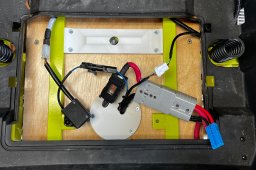
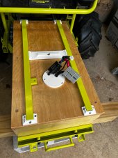
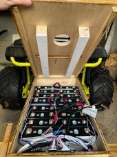
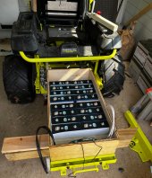
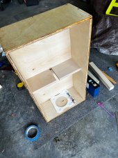
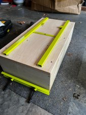
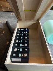
Well I am just about done with my battery build ( 100 Ah 16s CALB cells with Overkill BMS), save for a couple of dust shields... and I run into a problem. First, the battery worked well when driving my mower up and down the yard. No issues with the actual battery function, but I haven't yet mowed. First mow tomorrow. Pictures to follow later.

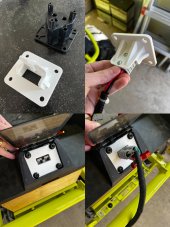
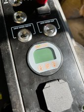
However, when I went to plug in my AIMS charger using the built-in quick Delta-Q connect there was a big arc with sparks and I think I fried the receptacle and plug. I'm getting resistance values in the mega-Ohm range across both the receptacle and the plug on the positive wire. Not really sure what happened, the charger was plugged in but the charger switch was off.

So I'm stuck considering 1) ordering a new receptacle and plug or 2) getting a whole new quick disconnect to charge. Any thoughts / opinions welcome. @AMDPower I know you had arcing with yours, did you solve this issue?
Mine was simply the charger connecting to the battery "live" and tripping the GFCI. I just make sure to attach the cable before turning the charger on and no problems occur.
 
I’m about to try out the “simple way” I have no time to build my own battery. My mower is brand new, it’s actually still at HD, I’m going to pick it up tomorrow. I’m going to order 4 of these battery's, the total with tax is about $1600. https://amperetime.com/products/ampere-time-12v-100ah-lithium-lifepo4-battery
They do free shipping and have a 3% off coupon. The battery has a built in BMS and they say they can run 4 in serial. Also the dimensions are the same as the OEM so it should be a drop in solution unless i’m missing something. The FAQs say it has a max 5120w load power. That would be the only thing i’m not sure of, what the mowers max load is, but I’m guessing it will be enough. I’m going to get a new charger and voltage meter as mentioned I should previously. Hopefully that is all I will need. I’m not sure how to wire up the charger snd meter yet, but I’m guessing it’ll be pretty straightforward. I’ll document the process and post here. I have to get the batteries shipped to a California address then shipped by boat to Hawaii so it may take about 3-4 weeks before I can do the swap.
Can you not return it? For the money of a new mower plus a battery conversion you could just buy an EGO or Greenworks zero-turn. Or wait until the new Lithium Ryobis come out (https://www.toolboxbuzz.com/lawn-ga...new-80v-lithium-zero-turn-riding-lawn-mowers/).
 
Can you not return it? For the money of a new mower plus a battery conversion you could just buy an EGO or Greenworks zero-turn. Or wait until the new Lithium Ryobis come out (https://www.toolboxbuzz.com/lawn-ga...new-80v-lithium-zero-turn-riding-lawn-mowers/).
That's a wild configuraton for the Ryobis! Looks like it has (3) 80V 10 AH batteries on-board for 30AH runtime and then you can use their regular 40V packs and add 4 of those at 12AH a piece. That should give a total of 54AH capacity which they claim is able to mow 4 acres (at 80V). Likely similar in capacity to our kits. I don't think I'd like the joystick control though. Might take some getting used to.
 
Thanks to all for your info and inspiration. Here is my addition to the list of converts. It was a pain in the butt trying to get the new meter in there and my dremel zipped onto the surface a few times. Still need to get the batteries setup and figure out where to put the Overkill BMS. I bought the 25 amp charger from Signature Solar so need to figure out charging connections.

IMG_9962.jpg
IMG_9961.jpg
IMG_9960.jpg
IMG_9963 copy.jpg
IMG_9964.jpg
IMG_9966.jpg
IMG_9965.jpg
 
Last edited:
Another shot inside. Had to make a busbar since I needed 4 longer bridges and only able to use the 3 from the old batteries D936C668-0361-4DAA-B89D-5F788A291086.jpeg
 
Still gotta clean up the rats nest but I’m almost there. I will try to change out the what looks like 12ga wire going from the charger plug connector to the main battery connection to a 10 gauge for the 25 amp eg4 charger 18376BE2-A633-4F1B-81D0-54FE580881A6.jpeg
 
I've finished my build and successfully mowed my yard with the new battery. 100 Ah cells, 16s Overkill BMS. Mowed my entire yard 0.8 acre on 22° slope using 30% of the battery capacity (80% → 50% SOC). One nice thing: with the old SLA OEM setup the fuel gauge would swing 20-30% depending on whether the battery was under load ( voltage vs SOC lookup table I presume ). I never knew that the actual percent was with the SLAs. With the shunt it's really nice knowing the exact SOC.

Max current while mowing with the new battery 108 Amps as reported by Overkill app, which did make me a little nervous. It must've been very brief since the 100A OEM battery fuse didn't blow. My old OEM battery was the 70Ah SLA. It might be placebo effect, but the mower seems peppier going up hills (shedding almost 200 pounds of lead and having more max current to work with I presume). I noticed no difference in center of gravity change: the mower doesn't seem any more likely to tip.
  • The design I used is a modded version of @rio 's brilliant build, here are the changes I made
    • added the middle lid notch to accept the steel lid brace (rough cut using a jigsaw)
    • used high quality 1/2" birch plywood for the sides and bottom, 3/4" for the lid and middle spacers
    • box held together with #6 screws and waterproof wood glue
    • middle spacers screwed into side
    • outside finished with 3 coats of spar polyurethane
    • 5 mm EVA foam (white Cosplay foam from Hobby Lobby) to pad the hold-down braces under the lid
    • 3d printed shunt holder, dust cap and stabilizers for middle brace, and the mains dust cap
    • used this enormous stepper bit to enlarge the hole for the shunt display, took 10 minutes with hand drill
  • I destroyed my OEM charging port by plugging in the AIMS Charger the first time causing a large arc from (we suspect) the inrush current filling the charger capacitors from the battery. I have a complaint filed with AIMS Corp to see if this is normal. Here's how I repaired:
    • removed OEM charger receptacle and plug
    • replaced with Anderson SB50 plugs
    • 3d modeled the receptacle to hold the SB50 onto the mower (see pics)
    • connected the blue wire from the lockout circuit to battery positive, permanently disabling the lockout
    • going to build a $20 protection circuit to prevent this moving forward using a diode and resistor in parallel
    • for now I have been disabling the battery using iOS app, then connecting AIMS charger, last turning battery on to charge without arcing
Here's a full Tinkercad of my build. I've been keeping SOC max 80% for battery life. AIMS charger set to charge LiFePo4 @ 15 amps. Planning to add a mechanical timer, estimate how long it will take to reach ~80% and have it turn off after that duration.

† With rio's help we reverse engineered the lockout circuit in case anyone wants to see how it works, and how I decided to connect the lockout circuit to battery positive, see pic.
 

Attachments

  • plug.montagejpg.jpg
    plug.montagejpg.jpg
    169.2 KB · Views: 124
  • 017.jpg
    017.jpg
    367.3 KB · Views: 115
  • 016.jpg
    016.jpg
    190.6 KB · Views: 118
  • 014.jpg
    014.jpg
    207.5 KB · Views: 115
  • 009.jpg
    009.jpg
    239.8 KB · Views: 108
  • 007.jpg
    007.jpg
    232.5 KB · Views: 100
  • 006.jpg
    006.jpg
    197.3 KB · Views: 91
  • 005.jpg
    005.jpg
    224 KB · Views: 88
  • 004.jpg
    004.jpg
    172.9 KB · Views: 105
  • LockoutDiagram-(1).jpg
    LockoutDiagram-(1).jpg
    86.2 KB · Views: 124
Last edited:
Forgot to mention the biggest challenges for me and how I addressed them on this build:
  • making sure that the bottom middle hole lined up with the middle hole of the steel frame and then the mower
    • did my best to center the steel frame notch in lid
    • put the steel frame on, then put the bolt through it
    • rotated the bolt in as large an arc as I could, scratching a ~2" circle in the bottom of the box
    • drilled a hole in the center of the scratched hole
    • put my box in the steel sled, slid it into mower and adjusted ends until hole lined up
    • had to completely remove one of the sled braces to get my box to fit
    • I would shave off an inch in length from my box if I had to do this again ( just have to make sure the box is long enough for frame )
  • drilling the shunt display hole
    • removed all controls from control panel, taking pictures of all connections first
    • clamped panel to a sawhorse
    • used large stepper bit above and a hand drill to ream it out
    • I think this would've been easier on a drill press
  • the metal clips used to hold the plastic mower shell together ripped out in several places from the drill torque, destroying the plastic
    • removed/replaced the shell screws slowly to minimize this
    • remove only as much shell as you need
    • measured original location of fastener holes
    • cut away mangled plastic
    • 3d printed some plastic tabs with taps that match the M6 screws
    • epoxied tabs to plastic shell, matching up location of taps to original
  • troubleshooting my dead mower: after the arcing mishap the mower wouldn't turn on
    • had a hunch that the OEM receptacle was damaged so badly that it wasn't reporting the correct charging state to the lockout circuit
    • with the blue wire to the lockout disconnected from the mower it wouldn't turn on at all (before or after the arcing)
    • so I guessed that the blue wire must require some voltage vs ground to report the not-charging state
    • @rio confirmed my theory by checking voltages on his undamaged wiring
    • it would be nice to have a functional lockout, but I would have to be very careless to drive off while plugged in
And new skills I obtained
  • using a circular saw first time
  • building, balancing, and testing a multi-celled battery
  • using a torque wrench
  • soldering a perfboard circuit
  • precisely 3d modeling a replacement for an OEM part
 
Last edited:
Back
Top