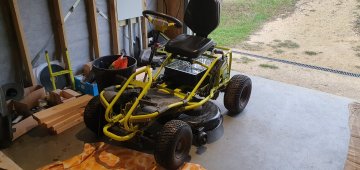
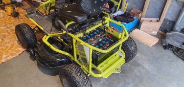
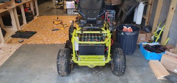
Finally enough stuff came together that I was able to complete this seemingly endless project. The below is what I've wired up:
View attachment 152732
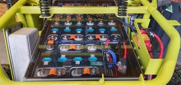
The idea of the circuit above is to use the capacitors in the mower to delay enabling a relay turning on and off the contactor in the mower. It seems that the key enables a 48 to 12v converter which then turns on the contactor relay. I don't know that the actual circuit in the mower is the way I have it above, it is just my way of thinking about it.
The key has 48v (52-56 actually with the LiFEPO4 batteries) on one side and that enables a path to the 48-to-12v converter. I disconnect the later and run it through a relay so that the 48-to-12v only gets turned on when the relay closes. In my wiring the key enables a path through a resistor (plus diode) that goes to the mower side of the contactor. When the key is turned on it slowly brings the capacitors up in voltage and eventually it reaches a level where the relay can fire. The purpose of the diode is to prevent the closing of the contactor from keeping the relay engaged (the other diodes across the relay coil is just good practice to keep the collapsing field of the relay from sending a reverse voltage spike into the circuit .. you will notice that Ryobi has one across the contactor relay coil). I've wired this up and there is about a 3-5 second delay after I turn on the key until the mower's contactor "clunks" into place and turns on the mower. When I turn off the key the mower shuts down immediately and then about 3-5 seconds later I can hear the relay that I added disengage.
The astute here may recognize a problem that I did not pre-think and rather found during testing. If you turn off the mower and then turn the key back on again prior to the relay turning off the capacitors in the mower won't have been brought back up to voltage and instead the contactor will immediately engage, look like a short to the battery, and the battery's BMS will shutdown. Argh. I am sure there is an elegant solution but I'm tired of working on this, the lawn has gotten too long .. for now I'm just going to be careful.
One other thing: in the above I show a 200 ohm resistor for the pre-charge leg. In my build I actually used 167 ohms 'cause I was cheap and ordered a 10-pack of 5w/500 ohm resistors. I put three in parallel for the "200 ohm" part (making 167 ohms) and two in parallel for the 250 ohm part that feeds the relay.
With that said, the parts I used are these:
Relay
Resistors
Diodes
With that relay you probably don't want to change the 250 ohm resistor much. The relay has a coil resistance of 86 ohms so the 250 ohm resistor makes the voltage across the relay max out at about 52 * 86 / (86+250) or about 13.3 volts.
FWIW I was hoping to use
this relay instead of the DPDT one linked above. It is a 48v SPST relay, I experimented with it, but alas did not have on hand the resistor I'd likely need to make it work. As I said, the grass is getting long and the wife unhappy.
I like the second relay 'cause it has a coil resistance of about 1.25k ohms. The problem with it is that cuts in at some very low voltage, significantly lower than the 48v for which it is rated. In addition it cuts out at an even lower voltage, something on the order of 10v. This means it will need something on the order of 2-4k ohm resistor in series to drop the voltage enough to make it effective (I did not have that and observed it had like a 15-20 second on/off delay).
One concern I have is that I don't know what the current rating is for the key switch. Perhaps a painful lesson will follow.
If anyone is interested I can post pictures later of the actual hook-up. Right now I should get to work.
")