JohnGalt1717
New Member
- Joined
- Dec 22, 2021
- Messages
- 102
Now we just need a DIY system that doesn't cost more than my carYouSolar makes a system similar to that that is stackable, but is is not relatively inexpensive DIY.
")


Now we just need a DIY system that doesn't cost more than my carYouSolar makes a system similar to that that is stackable, but is is not relatively inexpensive DIY.
There's many split phase inverters that handle AC Pass thru fine. Specifically Hybrid UL listed inverters, like the Schneider XW/SW lines. I assume they are able to do this safely by having complete control of the split phase transformer internally. They bypass/disconnect it during AC Pass thru to avoid this concern.I have to say, after watching these videos, and even looking at the units that do split phase, it really seems to me that AC passthrough is a bad idea.
Their design would start at $600 for just the rack let alone the battery, inverters, MPPT and charge controllers which since there isn't any pricing I'd guess is probably $45,000 for 30kW versus $12,000 DIY.Uh, how much do YOU spend on a car?
This could span a very large range, I think from $70 to $70,000,000
No, I snipped in a part of your post. You provided the context.You snipped out part of my discussion without context. If Will is an electrical Engineer then set the record straight and state it.
OK thenI am certified to operate electrical equipment up to 13800 volts but not an EE or ED(design)E so I will defer to those who are.
To many variables for my liking. If someone did design their system this way and they hit a temperature high enough to trip the thermal Switch once, twice, maybe three times in a year then there is a chance that the Enamel on the Transformers windings could be crystalized and starting to short internally. The unknowing home owner would have one Phase climbing in voltage and another dropping. I have seen the effects of windings going bad on AC units. The owner says their AC is tripping the breaker so someone changes the breaker to one that is 10Amps higher in value.--SNIP--
I think a 25A breaker feeding a sub-panel with hardwired auto-transformer is a reasonable thing to do. If over-current trips breaker, power to loads is shut off.
If there is a thermal protection device on the auto-transformer, that needs to go to a remote-trip of the breaker, not just interrupt power to auto-transformer the way it would for a heating load.
---SNIP---
I'm not going to pretend that I understand all of this but it sounds great. Off-grid energy systems have always had to adapt to on-grid components. This strikes me as a clean slate approach that focuses on the outcomes the system is trying to deliver rather than just making a bunch of on-grid stuff work in an off-grid situation.I have to say, after watching these videos, and even looking at the units that do split phase, it really seems to me that AC passthrough is a bad idea.
The better solution in my mind is to rectify the AC to 340VDC using a ideal rectifier (4 fets pulsed which can also apply PFC) which would generate a 0.5% loss, and then feed that into the SPWM inverter.
I.e. you have the following:
If you did this, you'd be VASTLY more efficient and need VASTLY less inverter power which would save a TON on the cost. (i.e. half/full bridges are always VASTLY cheaper and more efficient to build so even if you do need to convert voltages with DC, it's always cheaper than the copper in a transformer to do it purely AC and more efficient and easier than SPWM inverters.
- AC/DC mains input using a push/pull or Resonant LLC with transformer ideally that is isolated and UL listed. This outputs 340VDC to a internal DC bus. (about 95% or so efficient)
- Battery to DC Bus that boosts using a full bridge design at 98% efficiency whatever your battery voltage to 340VDC, which is required for the inverter anyhow. (this design is symmetrical, which is different than what is in there now which is forward only)
- MPPT that boost/buck as the second stage to the 340VDC bus internally. I.e. you use a half bridge to MPPT with shift and read, and then whatever the output of those maximized watts are, you buck/boost to 340VDC. This would actually be significantly more efficient with high voltage strings than MPPT to 48VDC AND once it's at 340VDC if you're running off of solar there is no further conversion and any excess after the inverter is taken care of will go out to the battery using #2.
- Dual 120VAC outputs capable of taking 100% of the wattage from the internal DC bus as needed to either leg. (and international markets would just be 240VAC doing the same).
- Output 340VDC (you can hack heat pumps and anything else that advertises "DC Inverter" to bypass the rectifier (or use the rectifier harmlessly) and feed this in without having to have huge inverters and save yourself a TON of in efficiency. Same with hot water heaters),
- Output 120VDC (ELV) for things like high dryers etc. (The great problem children of design, but ELV is unregulated up to 120VDC with less than 5% ripple)
- Output 48VDC for USB C 240V plugs. (I'd expect virtually all devices in the next 5 years like TVs etc. to only come with a USB C input because then they don't need UL certification at all, just FCC and any wall wart will work. If you switch the wall to be coming from 48VDC anyhow with USBC ports then you don't need the inefficient wall wart, the inverter nor the rectification. USB C will output 3.3, 5, 9, 12, 18, 20, 24, 28, 36, and 48VDC so you have everything that anything else DC would need so everything with a wall wart would be covered and work.
- Build an on wall DC/DC cart charger for CCS Type 2 that boosts/bucks the 340VDC to whatever the car DC voltage request is at 98+% efficiency thus eliminating the entire need for inverter and then rectification just to charge a car making it 15-25% more efficient which is a big deal on solar off grid.
This is a FET design in a pulsed environment so using GanFETS (600-900VDC max) for most of the design, and SICFets for the MPPT (1800VDC max) works really well and isn't very expensive because the pulsed continuous load rating on these FETs is in the 100s of amps per FET on a 6MM copper board trace.
Honestly thinking about designing one of these as a modular design in a rack... The only part that gets expensive is the AC/DC mains input because of the UL and FCC certification to do it right. Given ENNOID-BMS, this becomes super compelling in design because we can easily scale our batteries to higher voltage with this design and reach better efficiencies on the bus over time as we can afford more batteries, while minimizing inverter power required.
To many variables for my liking. If someone did design their system this way and they hit a temperature high enough to trip the thermal Switch once, twice, maybe three times in a year then there is a chance that the Enamel on the Transformers windings could be crystalized and starting to short internally. The unknowing home owner would have one Phase climbing in voltage and another dropping. I have seen the effects of windings going bad on AC units. The owner says their AC is tripping the breaker so someone changes the breaker to one that is 10Amps higher in value.
Unit works fine for a few days and then poof the compressor is dead. With an Autotransformer I could see this becoming a run away event that suddenly increases the voltage on one leg long before a breaker trips.

 www.currentconnected.com


His brief comment in that video was, use an internal transformer all in one. Don’t use external solutions. Distributors, and some YouTube creators are realizing the liability box they have placed themselves in. Companies like Growatt have no business selling products, that can easily kill people, that are mislabeled for region and incorrect instructions. We love cheap stuff, but this inept behavior will kill the DIY market When people start complaining to regulators.NEW VIDEO BY IAN
Thanks Ian.
I hope some of these naysayers finally understand what they are dealing with.
Nice! A "smart" autotransformer with protections.Full disclosure: I am a Victron distributor and know the products I supply very well, one of them solves the greatest (99%) majority of issues in this thread.
Victron sells an autotransformer properly designed to handle all issues Ian stated. I believe it is a good solution for all issues noted in the thread, INCLUDING the issue with circulating currents when on-grid. I'll summarize here:
This is how to do an autotransformer right.
- 100A Main breaker has shunt trip.
- 240v (Without neutral) Power from all inverters can feed into the 100a Main breaker, this is the main disconnect for all incoming power.
- The transformer has internal temperature sensor which shunt trips the main breaker, in case of thermal OR electrical overload, shutting down all loads that feed through the transformer, instead of shutting down the neutral.
- The enclosure also has a fan for better cooling.
- The circuit inside has a relay for N-G bond, triggered by the inverter when going into pass-through mode. In pass-through the utility bond is used, so a double-bond never exists because the relay is open in utility mode. In off-grid mode the system is separately derived, so a new neutral/ground bond IS NEEDED for the autotransformer. This relay eliminates the chance of circulating currents when on-grid.
- The transformer MONITORS the winding current, if the winding current exceeds the transformer's rating, then the main is again, shunt tripped, gracefully shutting down everything.
Let's talk about the practicality though. These units retail at $784. If you are already invested in the inverters, this is a way to fix the issue on your hands if you can't return your inverters, assuming you have the inverter with the neutral-ground bond removed. Take the added after-the-fact cost as a learning lesson that the cheapest solution upfront isn't always the best solution long term.
As an added bonus some Growatt units have option #24 that allows the external dry contact to control a ground-neutral bond relay (see below). Some models of Growatt units have this option removed. Without this option of external ground-relay control, you do still have the issue Ian described of the circulating currents when passing through Grid power, BUT it is still protected thermally and from overcurrent in a safe manner.
If you are going for a NEW system, this is a waste of money, because as numerous others have mentioned, you can get a more-capable unit with a proper neutral for like $200 more, and then you DON'T NEED to mess with transformers at all.
I just got a new camera, so I plan to record a video tomorrow to better describe the features of this autotransformer, and get a visual for those of you on this thread to see.
Link to SAFE autotransformer, readily available:
Victron Autotransformer - 120/240V - 32A or 100A | Current Connected
Enhance safety and efficiency with the Victron Autotransformer. Step up, step down, and balance your split phase output effortlessly.
Option 24:
View attachment 81279
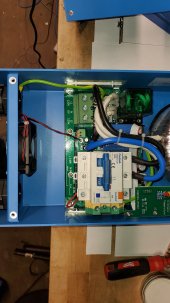
Pictures inside Victron Autotransformer:
View attachment 81282
View attachment 81281
Hopefully this "Armchair" was of some value in this post.
UPDATED:
Issue #1: neutral-ground bonding, we have had these units ship under the American version, The PCB is not the same, some others here show removing the screw bond, but then find that the board still has a conductor trace that leaks to ground. This is why you need to buy these from an authorized American distributor, as listed on growatt-america.com
Issue #2 Neutral conflict between grid and off grid autotransformer. we are loading a schematic on this one: IF YOU ARE TAKING YOUR WHOLE HOUSE OFF GRID THERE SHOULD NEVER BE A NEUTRAL PASSED THROUGH FROM THE GRID. this is true for the split phase 12kW and 6kw inverters as well. the bottom line here is that all that is needed from the grid input is L1/L2. A dedicated ground rod is needed to bond to neutral of the off-grid autotransformer.
I really want to see some pictures of this from someone who has a unit and can pull out the board.FYI everyone.... Post #1 was updated as of last night.
I'll do it once i get my LV6548s... ETA end of febI really want to see some pictures of this from someone who has a unit and can pull out the board.
I would have thought that signature solar would have provided pictures.
So are we going to see the pictures of the so called the 'American' version even though the sticker and the user manual still show as SPF-5000 ES?UPDATED:
Issue #1: neutral-ground bonding, we have had these units ship under the American version, The PCB is not the same, some others here show removing the screw bond, but then find that the board still has a conductor trace that leaks to ground. This is why you need to buy these from an authorized American distributor, as listed on growatt-america.com
Issue #2 Neutral conflict between grid and off grid autotransformer. we are loading a schematic on this one: IF YOU ARE TAKING YOUR WHOLE HOUSE OFF GRID THERE SHOULD NEVER BE A NEUTRAL PASSED THROUGH FROM THE GRID. this is true for the split phase 12kW and 6kw inverters as well. the bottom line here is that all that is needed from the grid input is L1/L2. A dedicated ground rod is needed to bond to neutral of the off-grid autotransformer.
You can keep all of your grounds including the utility bonded, several big-name hybrids with transformers do this as well, like QCells, Delta and SolarEdge. If you are concerned about the boogeyman transformer mis-winding idea, then theoretically you could separate just the utility meter as in the below diagram (NOT REQUIRED/ THEORECTICAL)
As far as autotransformer size is concerned let's take a second and discuss what the ratings mean. the "imbalance power is reflective of the balance between the total 120v loaded L1 and L2 legs, NOT the total kW of 120v loads.
-Any 240v loads like an air conditioner, heater or pump pull evenly and therefore have ZERO load on the auotransformer
2x 5000es + 1 transformer with 5000w on L1 and 5000w on L2 has a transformer load of 0 watts, not 10000w,
5000W on L1 and 4000w on L2 is a load of 1000W on the transformer, not 9000w
-A 5000es + 1 transformer with 3kw of imbalance can run a max power split of 4kw/1kw on L1/L2
-2x5000es + 1 transformer can split max at 3.5kw/6.5 on L1/L2
This beats the imbalance tolerance of sol-ark, MPP, Growatt LF and most others, that's why this autotransformer has become a common trick by the Sol-Ark clientele
You can't run an unlimited amount with 1 transformer and per the manufacturer you need breaker protection, if you combine your inverters, transformers and 240v loads on the ac out panel and then feed your 120v loads panel you will be able to achieve full protection (VIDEO COMING)
If you have more than 5kw of 120v then odds are you need a second transformer.
Most off-grid folks have the 120v loads under control because they plan their lifestyle before going of grid. This design is a huge win on cost because the major off grid loads, like AC, Dryers, Ovens, and other large 240v loads now only cost $900 for 5kw with a 6kw 450v solar charger built in that needs no combiner box.
View attachment 80254
That will be great!I'll do it once i get my LV6548s... ETA end of feb
I really want to see some pictures of this from someone who has a unit and can pull out the board.
I would have thought that signature solar would have provided pictures.
Yes I find it really strange that they say there is no Trace but did not provide a picture. I would think after all of this bad PR they would want to post a picture ASAP.The fact that you and several others have requested this over a week ago, and they have been testing for several days and did not show pics of the board as soon as they got in there leads me to assume we will not like what we see.