diy solar

diy solar

Safe Grid Use of the 5000ES and transformer

When it comes to a direct lighting strike.
All that you can do is try and hope.
 
When it comes to a direct lighting strike.
All that you can do is try and hope.
Mine wasn't direct in a sense, the strike followed that low resistance of the wire. Makes me wonder about that #6 copper laying in the ground. What is really something was a new service entrance properly bonded and with a brand new copper ground rod installed at the time just about 3 years prior. Why didn't the energy head to the ground rod instead of the neutral busbar?

Sometimes maybe the "rules" weren't always the best thing ever adopted. LOL
 
The code updates every 3 years. Some things are added. Some things are modified. And some things are removed. We humans can't learn from our mistakes, until we make them. lol
 
Hi, I'm new to the form... and honestly I could only spend 6+ hours trying to parse through the 900+ posts on this thread looking for an answer. All of the answers and replies get intermixed with "that will work" right after someone says that a different solution will not work. I understand some options cannot be made to work... but that doesn't mean no option will work.

To help summarize the past 900+ posts and narrow the answer for people who already have all or part of an SPF 5000 ES system:
  • SPF 5000 ES from SS, or circuit board ground screw removal (no internal bonding between ground and neutral on AC input, which seems to be something someone can confirm with a DMM)
  • 120VAC loads required, but not specific to any transformer(Growatt At5000, the solar edge transformer, or isolation transformer)

What are safe options for a system configuration to use the US grid as a backup and or input?
What are any associated caveats?
 
Hi, I'm new to the form... and honestly I could only spend 6+ hours trying to parse through the 800+ posts on this thread looking for an answer. All of the answers and replies get intermixed with "that will work" right after someone says that a different solution will not work. I understand some options cannot be made to work... but that doesn't mean no option will work.

To help summarize the past 800+ posts and narrow the answer for people who already have all or part of an SPF 5000 ES system:
  • SPF 5000 ES from SS, or circuit board ground screw removal (no internal bonding between ground and neutral on AC input, which seems to be something someone can confirm with a DMM)
  • 120VAC loads required, but not specific to any transformer(Growatt At5000, the solar edge transformer, or isolation transformer)

What are safe options for a system configuration to use the US grid as a backup and or input?
X # of Growatts that either have the ground screw removed or come from SS. (best is to take the main board out and neuter the pin that the ground screw connects to so that there's no chance of arc if you're using ones not from SS)
1 or more Growatt auto-transformers (or someone else's doesn't matter as long as it takes 240V in and outputs a 120V neutral center tap) Generally 5000 watts is enough for an even remotely well balanced house.
240V incoming from Grid WITHOUT neutral (just both hot legs) into the Growatt AC IN
240V outgoing from the Growatt.
Make sure that you have the phases aligned. IE: Red in/Red Out, Black In/Black Out and every inverter in parallel lined up in your panel so that all phases are in sync for both grid and inverting (the inverters will correct but still...) or you'll get a hard switch from the Growatt that UPSes etc won't like.

If you are going to have some sort of switch that bypasses the Growatt and goes directly back to the grid power, then you MUST either have the auto-transformer still hooked up and NO NEUTRAL FROM THE GRID OR you MUST switch the neutral too using a 3 pole, double throw switch ($$$$!!!)
In short, you're fine as long as the grid's neutral is not connected anywhere while the growatts are also connected.
 
Last edited:
The Growatt 5000es is made for the U.S. market and is sold by other retailers, do not try and modify the wrong model.
 
X # of Growatts that either have the ground screw removed or come from SS. (best is to take the main board out and neuter the pin that the ground screw connects to so that there's no chance of arc if you're using ones not from SS)
1 or more Growatt auto-transformers (or someone else's doesn't matter as long as it takes 240V in and outputs a 120V neutral center tap) Generally 5000 watts is enough for an even remotely well balanced house.
240V incoming from Grid WITHOUT neutral (just both hot legs) into the Growatt AC IN
240V outgoing from the Growatt.
Make sure that you have the phases aligned. IE: Red in/Red Out, Black In/Black Out and every inverter in parallel lined up in your panel so that all phases are in sync for both grid and inverting (the inverters will correct but still...) or you'll get a hard switch from the Growatt that UPSes etc won't like.

If you are going to have some sort of switch that bypasses the Growatt and goes directly back to the grid power, then you MUST either have the auto-transformer still hooked up and NO NEUTRAL FROM THE GRID OR you MUST switch the neutral too using a 3 pole, double throw switch ($$$$!!!)
In short, you're fine as long as the grid's neutral is not connected anywhere while the growatts are also connected.
Is there a wiring diagram posted or otherwise that could demonstrate this solution?
 
The Growatt 5000es is made for the U.S. market and is sold by other retailers, do not try and modify the wrong model.
Can't this concern be resolved by any user with a DMM to identify if each unit they have is a US variant or a European variant?
  • 'Continuity' between any of the 3 inputs = Europe (Modification needed for US grid input)
  • 'Open' between each of the 3 inputs = US (No conversion)
As always, correct me if I got any details wrong but please don't forget to address the main question.
 
Last edited:
In short, you're fine as long as the grid's neutral is not connected anywhere while the growatts are also connected.
If the grids L1 and L2 are being used. The grids neutral must also be used. All current must return to the source. If you don't provide the proper path, it will try to find another path. (Ground conductor, metal structures, people)
 
All of the answers and replies get intermixed with "that will work" right after someone says that a different solution will not work. I understand some options cannot be made to work... but that doesn't mean no option will work.
240V incoming from Grid WITHOUT neutral (just both hot legs) into the Growatt AC IN
240V outgoing from the Growatt.


If you are going to have some sort of switch that bypasses the Growatt and goes directly back to the grid power, then you MUST either have the auto-transformer still hooked up and NO NEUTRAL FROM THE GRID OR you MUST switch the neutral too using a 3 pole, double throw switch ($$$$!!!)
In short, you're fine as long as the grid's neutral is not connected anywhere while the growatts are also connected.

... and I'm going to say that does not work safely.

As I've written before (among the 600+ replies to this thread, or the 6 (?) other threads on same topic),
there will be "objectionable" current in ground wire (if connected back to grid), or neutral will take on voltages higher than ground, or "ground" will be higher than actual ground, which you may even discover while sitting in a bath tub.

Only judicious application of isolation transformers will make it work correctly and safely.
Simplest is an isolation transformer on the output. I'd rather put that on input and have auto-transformer on output; these can be sized for less no-load power consumption (something I've been studying and experimenting with extensively for 3-phase step-up applications.) Transformers, especially that will handle the power and not waste much power are not cheap!

If the grids L1 and L2 are being used. The grids neutral must also be used. All current must return to the source. If you don't provide the proper path, it will try to find another path. (Ground conductor, metal structures, people)

Exactly!

Except if you do the following, which is the safest way: Connect grid to 240V primary of an isolation transformer. Connect secondary to Growatt.
What I'm not sure of, can't say without seeing a schematic of Growatt, is if we connect transformer center-tap to neutral of growatt, use an auto-transformer after Growatt, or ...
 
Transformer after the Growatt is better.
240v grounded system through the Growatt to the isolation transformer. Bonded transformer secondary for a grounded system after.
This way everything is protected by a grounded system.
 
It just means you need a transformer big enough for all 240V loads as well as 120V.
(could have saved money and losses with one 240V load panel, and a breaker-protected 120/240 load panel with auto-transformer.)

There are a few auto-transformers offered for inverters. Got any leads on efficient isolation transformers for use downstream of a battery inverter?
What I'm finding is excessive no-load current draw because they're size to save on cost, and partially saturate so current spikes up.

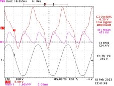
Like this waveform driving a 20kVA, 200V delta transformer with my 120/208Y inverters. It shows 6.3Arms per 120V leg. That's 750 VA of reacative and real power per 6.6 kVA of transformer, similar to what the GroWatt would see:

Olson 120-208 into 200 delta 021823 1059.jpg

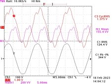
My solution is to run windings at half their intended voltage. If a transformer has two 240V primary windings, I put 120V across each.
The transformer for which I captured the above waveforms was meant to take in 200/230/460/575V delta on the primary and produce 277/480Y secondary.
What I've done is to rewire primary as WYE, and I apply 120/208Y to the 200V windings, so 460V windings act as auto-transformer and make 277V. Still good for 20 kVA due to happenstance (ratios of applied/designed voltage and auto-transformer step-up ratio.)
That dropped current to 1/4 as much.

Olson 120-208 into 200 wye 021823 1122.jpg

High reactive load on an inverter will increase its no-load loss.
 
It just means you need a transformer big enough for all 240V loads as well as 120V.
Does it need to be one big transformer, or can you stack them in parallel like the 5000 ES to increase capacity as your system increases?

How do you size the transformer(s), do you:
  • Match the size of the Transformer(s) with the size of the Inverter(s)?
  • Match the size of the Transformer(s) with the max surge of the Inverter(s)[to accommodate motor start up, etc.]?
  • Some other way?
 
Transformer after the Growatt is better.
240v grounded system through the Growatt to the isolation transformer. Bonded transformer secondary for a grounded system after.
This way everything is protected by a grounded system.
I'm assuming you could use this design to have multiple options to maximize flexibility:
  • Have a transfer switch that moves the 240 from the output and when needed bypass the inverters and feed the transformer directly without worrying about the ground
    • (Not efficient on grid, but good if needed to keep the lights on if the solar system needs maintenance)
  • Replace grid input with a grounded generator and still have the system retain it's own ground.
    • This might even allow a transfer switch to change between generator and grid power feeding the inverters.
 
Parallel might work, but could share a bit unevenly. Especially if different models. I only occasionally see an eBay lot with several of one model.

Nominally same VA rating as inverter ought to work.
At full load, it is going to run HOT. Look at the labels; some are rated to run at 150C or 200C (innermost windings; I expect outside of enclosure to be safe to touch.

You don't need to size it for surge. A transformer rated 3% puts out +3% voltage under no-load, -3% under full load. That would drop to -9% under 2x load, which is probably all your inverter can deliver. If your 5kW inverter could deliver 25kW surge, then -27% under typical 5x starting surge for a motor.

A heavier transformer may run at lower temperature rise, and lower no-load current. A higher VA rated transformer will run cooler; power dissipation in winding goes as square of current, so 7.5 kVA transformer carrying 5kVA would be (2/3)^2 or 4/9 as much power dissipated.

If you want an auto-transformer, don't try to use two 120V secondary windings. They can draw much higher current than you expect.
I recommend getting a 240/480 to 120/240 transformer, connecting the two 240V primary windings in series, and using them for 120/240V auto-transformer. Unfortunately, you're not likely to find one that can be used at 1/2 voltage as an isolation transformer. If you find one for 240/480 primary and 240/480 secondary, that would do it. Used at half voltage (full current), it will only be for half its VA rating.

It's OK to be inefficient on grid, which is why I'd rather have a transformer on input to inverter. Inverter on output has to be powered the entire time inverter operates.
 
(could have saved money and losses with one 240V load panel, and a breaker-protected 120/240 load panel with auto-transformer.)
What do you mean by this?
This statement feels like what Signature Solar recommends in their video and schematic. They seemed to suggest that having a 2 pole breaker on the output makes a difference when an over current on either leg will trip the other side... or cuts power to the input or something.

Is there a variation/tweak you can make to keep the neutrals/grounds happy and safe, while not having 240v on one 120 leg or the other?
  • Like having a multi-pole breaker with one pole connected to the output, and the other half going to the input of the auto transformer, and the other side connected to the output?
... or is an isolating transformer before or after the only way to safely handle the ground/neutral issue under off-nominal cases (bad load balancing, switching breakers, short to ground, short circuits at any point, etc)
 
Back
Top