diy solar

diy solar

Scratching my head wondering why the solar isn't keeping up.

lt170chevelle

New Member
Joined
Jan 4, 2024
Messages
7
Location
Trenton TX
Hello, new guy here. Been off grid for over a year now on my ever expanding solar setup. Been trying to figure out if my system just is not big enough or something else. Like most beginners I have mostly cheaper end equipment. Would like to here any input or advice on this setup on why it isn't keeping up or what solutions I may need to pursue.
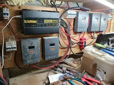
5 powmr 60a mppt solar chargers
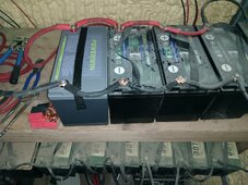
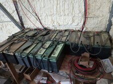
25 various brand 100ah LI 12v batteries wired parallel
Right around 4000 watts of solar array single faced 100w panels and one 200w panel on each string ,wired in parallel, with exception of 3 250w bifacial wired in series to one dedicated controller
Also have one of the useless small wind turbines with a mppt controller on it. "400watt" but likely less than 100w true output
2000w sine wave inverter

My current load/usage is 350w-400w constantly 24hrs a day.

Sunny days all charge controllers and inverter show a good 13.5v all day, but overnight the battery bank gets drained and system shuts down.

I've been slowly adding batteries as I can afford them but I just did the math and it seems should have more than enough to handle the usage.


Any advice greatly appreciated.
 

Attachments

  • IMG_20231224_173201.jpg
    IMG_20231224_173201.jpg
    349.2 KB · Views: 58
  • IMG_20231224_165224.jpg
    IMG_20231224_165224.jpg
    238.6 KB · Views: 59
Throwing batteries at the problem if half of them don't work right is no good. I would break the batteries into small groups or individual and start figuring out which ones are pulling their weight and which ones are not, otherwise you could have good batteries trying to charge bad batteries and vice versa.
 
charge controllers and inverter show a good 13.5v all day, but overnight the battery bank gets drained and system shuts down
You need to get to a higher voltage than13.5, you need to get to at least 13.8 volts. In addition cell balancing does not start to function until the cell volts are greater than 3.40 volts for most BMS. This needs a battery voltage in excess of 13.60 volts, ideally higher.
25 off 100Ah batteries in parallel sounds a nightmare to get balanced charge into them.
I guess the batteries are not being charged equally and also have become inbalanced internally thus reducing capacity.Screenshot_20240104-231107_Drive.jpg
 
various brand sounds like the problem here...ideally they should all be the same brand and type. Mikefitz is correct..
 
Is that 32kWh of individual 12v batteries? Wow!
Can you share pictures of how that's set up? There's likely some improvement possible there, but I doubt that's the biggest deficiency.

The ratio of 4kW of solar to 32kWh of storage is unusual light on solar in my opinion.

Can you share how the panels are set up? Sounds like they are randomly connected.
I think you probably has some improvement possible by reorganizing how your panels are connected.

Without more information, I'd say you need more solar. It's possible you have some "free" solar by just improving what you've already got, but you might need to buy more.
 
Thanks for all the replies.

I have 25 of the 100ah lifep04 batteries wired in parallel at 12v.
Wired positive on one end and negative on the other end which from what I've read was the best way to evenly use and charge the batteries. Just recently started upgrading additional added wiring and main feed cables to 0/1g wiring.

Attached is one of the latest pictures , and the other is when I was still building the bottom battery shelf..for reference

The panels are all mounted on the roof besides the three 200 watt panels I recently added to the south facing wall. The roof pitch is on an east and west facing direction so not totally ideal.

I've been planning on doing some additional panels on the ground and get them positioned right this summer to help.

As far as the charging voltage it's preset from manufacturer on these Chinese solar chargers for the lithium battery option and unfortunately have terrible owner manuals on them. They do have a custom preset option but was leary on trying to up the voltages and damage anything.
I was under the impression these are supposed to be charging at 14.7 volt initually before It starts ramping down but I never see it higher than 13.5 or 13.6 during the day.
 

Attachments

  • IMG_20231224_165224.jpg
    IMG_20231224_165224.jpg
    238.6 KB · Views: 35
  • IMG_20230426_164415.jpg
    IMG_20230426_164415.jpg
    211.1 KB · Views: 35
14.7 should cause over voltage disconnect on the batteries, that's too high.
If your currently charging to 13.6 max, you need more PV. Or maybe there is a better way to connect your panels. How are they set up?
 
I have 25 of the 100ah lifep04 batteries wired in parallel at 12v.
Wired positive on one end and negative on the other end
There are far worse and far better ways to wire.

Read the first 4 posts to get the idea: (not sure how to scale to 25 batteries!)
 
I would like to focus on the panels for a bit - to figure out if you have a wiring penalty going on.

What we need to know is exactly what is connected to each SCC (solar charge controller). We need to know the following specs for each panel:
Voc_______
Vmp_______
Imp_______

So if the 100w panels are the same - great. If they are different- put each panels spec down.

Then how do you have them connected-series? Parallel?

I am almost sure the strings with the 200w panels are having a wiring penalty- how big - we will have to do the math.
 
Last edited:
With 25 batteries in parallel you have a 12v 2500ah battery- it will take a LOT of solar to top off that battery bank.

Also do you have a shunt based battery monitor for the entire battery? Something like a Victron Smartshunt or BMV712? If you do please post the last 10 days (or so) of SOC trend graph. (If you don’t have a battery monitor- consider getting one and look very closely at the Victron).
 
I have not installed a shunt yet for monitoring.But do plan to.
As far as the panels, all are wired with 10g wire to dedicate chargers for each string.
The 3 bifacial solar panels are 200w each wired in series to one controller.
The other 4 chargers have a string of one 200w panel(single faced) and 6 100w panels each wired in parallel each.
The only specs I have are
200w bifacial OCV 28.1v SCC 9.12a
100w OCV 22.8 SCC 5.45a
The other 4 200w single faced panels I can't seem to find the specs for them.
 
Last edited:
Yes I would start separating the batteries a few at a time for separate testing. Amps should flow in freely until it reaches 14.2 volts. Likewise the battery should supply power down to 13.0 volts. If you have a consistent load for testing watch the time as they should be about the same as they are rated same capacity.

Yes bump the solar controllers to 13.8 - 14.2 zone asap.
 
One of the solar issues may be your SCC (solar charge controller) wants voltage between 20 and 80v. The parallel strings may not be providing enough voltage to start the SCC’s until later.

The three 200w BiFacial in series may also be an issue- with a Voc of 28.1 *3 = Voc of 84.3v. I could not find good specs on Powmr’s website other than it said voltage range of 20 to 80 volts. With the cold of winter that will push voltage up, some high voltages damage (ruin) SCC - others just turn it off until the voltage drops. On this SCC, I would recommend reconfiguring to a 3p arraignment. You will then have a Voltage of approx 25v and a current of under 30amps. Better and safer for the SCC.

Because you cannot find the specs for the 200w panels. I would hook them up as 2s2p string into one SCC. That way there is no electric penalty. There will be a clipping penalty because this string has 800w of solar, but your SCC can only produce 720w of power. The only time that will happen is when conditions are perfect (around noon in June).

The other 24 100w panels, I would hook up 8 panels per SCC in a 2s4p arrangement. This way you will will not have any electrical penalty- just clipping.

On all solar strings with more than 3p they must have a fuse on the positive line as you combine the strings (look on the panels for the fuse size -usually 15a). They make MC4 fuses that will just clip in.

I wanted to figure out the penalty for having different panels hooked together- but you couldn’t find enough info on the panels. Here is how you do it:

Volts * Amps = watts
Use Vmp and Imp for these calculations:

In series you add volts and use the lowest amps

In parallel you add amps and use the lowest volts.

Because of the way it was hooked up in parallel- that 200w panel was getting dragged down to probably 125 to 150watts. That’s why I recommend changing your arraignments.

If you need to replace any of those SCC’s - you can get better ones that spell out the specs specifically. Look at a Victron 100/50 or a 150/60.

Anyway Good Luck in this area.
(Did this long novel make sense- are there any areas I need to explain better?)
 
One more wiring item to consider - Battery’s.

The last battery in your string will have LOTS of connections for it to go through before it gets to the battery. So your first battery’s impedance and the last one will be WAY different.

Get some high quality bus bars - must be Copper (not brass), and put 5 batteries on a string in parallel- then 5 strings on the bus bar.
Or…
You could get a couple feet of 1/4” x 1” tin plated copper and make your own bus bars. Maybe have 10 bolts on the bus bar and then 2 or 3 batteries per bolt. That will help reduce all the connections in your last battery - evens them out. Then you have a nice “all positive” spot to hook up a class T fuse and a “all negative” spot to hook up a shunt for the battery monitor.

After the fuse & shunt - make another (pos and neg) bus bar for the chargers and loads. That should help with spots for fuses.

Good Luck
 
Dont mix old batteries with new. You will only have the performance of the worst one.
Those aren't lead acid batteries, so this shouldn't apply here.

The other 4 chargers have a string of one 200w panel(single faced) and 6 100w panels each wired in parallel each.
As others have said, this mixing of mismatched panels on the same charge controller is less than ideal and likely limiting your solar energy harvested.
The only specs I have are
200w bifacial OCV 28.1v SCC 9.12a
100w OCV 22.8 SCC 5.45a
The other 4 200w single faced panels I can't seem to find the specs for them.
If Rocketman has the correct charge controller specs (you should verify this or post them here) his recommendations in post #15 seem like an improvement. It would be good to measure open circuit voltage on each string before connecting it to the charger controller, just to verify the guesses on panel specs are in the correct range.
 
Based on the picture posted it is likely that only the first few of the 25 batteries will be fully charged. The 15-20 batteries down the line will get less and less charge towards the end of the line. What the SCC will see is the voltage of the first few batteries. When those batteries reach the voltage set by the SCC the SCC will stop charging. But the rest the of the batteries will have a much lower voltage and will not ever be close to full.

When discharging at night the inverter only sees the voltage of the first few batteries. It will shut down when that voltage drops to its cutoff limit.

Here’s Will Prowse discussing this issue with only 5 batteries in parallel. With 25 batteries in parallel, the problem you are facing is multiplied.

 
Right around 4000 watts of solar array single faced 100w panels and one 200w panel on each string ,wired in parallel, with exception of 3 250w bifacial wired in series to one dedicated controller

The wiring of your solar panels isn't exactly clear. Please describe each string. I suspect that you might be getting only 200 watts out of each string, and the 100w panels are not utilized effectively.
 
Back
Top