Like what? Give me one possible scenario where this can be caused by the BMS.
The cells' voltages are measured correctly. I've checked that with a multimeter. The total battery voltage also. The issue seems to be on the inverter side - battery voltage is OK, but during discharge, the inverter sees a voltage spike. Give me one possible scenario for that. And this is not 0.1s voltage spike, but like 3-4-5 seconds spike. I have no logical explanation of how this can happen yet, so I'm leaning toward an inverter issue.
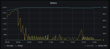
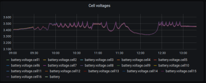
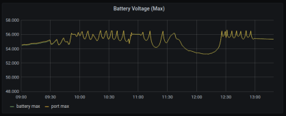
The cells' voltages are measured correctly. I've checked that with a multimeter. The total battery voltage also. The issue seems to be on the inverter side - battery voltage is OK, but during discharge, the inverter sees a voltage spike. Give me one possible scenario for that. And this is not 0.1s voltage spike, but like 3-4-5 seconds spike. I have no logical explanation of how this can happen yet, so I'm leaning toward an inverter issue.