diy solar

diy solar

Series string shading summed up in 4 pictures

The way I understand it is.
Damage from shading is over time.
If the panel receives a lot of shading. The bypass diodes are used a lot. Eventually the bypass diodes fail. Then, the cells are forced to carry the power. Which causes them to heat up, daily. Eventually, they fail. (Possibly even catch fire)
In the few stories I have read about this. The process takes place over several months or years. Depending on the amount of daily shading.
 
It seems that the MPPT's algorithm falsely locked to a local optimum point on V-I curve instead of a global optimum that is at much lower voltage (less shade panels). Perhaps other brands MPPT might not experience the same problem. My SMA inverter doesn't have this problem. I can try this situation on Growatt inverter.
There are many way of achieving MPPT ... many algorithms, some are more efficient and complex then others...
 
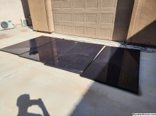
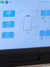
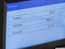
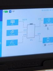
Another example of partial shading a string lowering total output substantially. The minimum voltage for MPPT is 120VDC. But even at 155 (nearly VOC obviously), it's not enough to bypass the shaded panel. In a few more minutes they will be running at full output.

20230903_095609.jpg
20230903_095629.jpg
20230903_095645.jpg
 
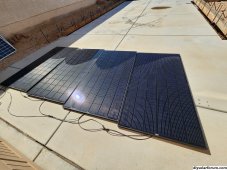
Now you'll notice that the sun passed the center line of the panel exposing those cells and allowing current to flow. We now have increased output:
View attachment 165811
View attachment 165812
In the first picture, the middle and outermost 3rd panel are completely blocked, so the best an MPPT could do is get:

Vmp x (3-1/3) - 2 x Vdd
(Vdd being the bypass diode drop voltage of ~0.5-0.7V per diode).

You said your MPPT minimum is 120V but I’m guessing that even if two bypass diodes activated the only way the remaining 3-1/3 panel string could exceed that voltage was to get way up close to Voc (meaning current is being choked off by the high voltage on each panel rather than the shade).

In the second pic. the middle 3-rd panel is mostly free of shade. Inner column is clear and the outer column is ~2/3 to 3/4 clear.

So now with only 1 bypass diode activated, voltage will increase to over:

Vmp x 3-2/3 - 1 x Vdd which at a minimum, allows voltage on each panel to back off from Voc by ~Vmp/9 closer to Vmp.

The partially-shaded column is reducing current to a maximum of ~2/3 to 3/4 Imp but that’s far higher than the current you had in the first picture where voltages had to increase close to Voc to reach the 120V minimum of the MPPT…
Outermost third? Third panel is in full sunshine. Three panels are completely exposed to sun. It's only the fourth panel that is shaded.
 
An
In the first picture, the middle and outermost 3rd panel are completely blocked, so the best an MPPT could do is get:

Vmp x (3-1/3) - 2 x Vdd
(Vdd being the bypass diode drop voltage of ~0.5-0.7V per diode).

You said your MPPT minimum is 120V but I’m guessing that even if two bypass diodes activated the only way the remaining 3-1/3 panel string could exceed that voltage was to get way up close to Voc (meaning current is being choked off by the high voltage on each panel rather than the shade).

In the second pic. the middle 3-rd panel is mostly free of shade. Inner column is clear and the outer column is ~2/3 to 3/4 clear.

So now with only 1 bypass diode activated, voltage will increase to over:

Vmp x 3-2/3 - 1 x Vdd which at a minimum, allows voltage on each panel to back off from Voc by ~Vmp/9 closer to Vmp.

The partially-shaded column is reducing current to a maximum of ~2/3 to 3/4 Imp but that’s far higher than the current you had in the first picture where voltages had to increase close to Voc to reach the 120V minimum of the MPPT…
And yeah that's what I said. That's why I took the picture so you could see that. That was the whole point of the post
 
Outermost third? Third panel is in full sunshine. Three panels are completely exposed to sun. It's only the fourth panel that is shaded.
Oh, sorry, I was referring to the outermost 3-rd (outermost 1 columns) of the one shaded panel (not the outermost 3-rd of the entire array…).
 
An

And yeah that's what I said. That's why I took the picture so you could see that. That was the whole point of the post
The pictures are great because you’ve got a near-ideal vertical shade pattern that first blocks 2 3rds of one panel corresponding to 2 bypass diodes and then pulls back so that only the outermost 1/3 panel is completely shaded and the middle 3rd is partially-shaded with a uniform % across one column.

If you were to track power output during that part of the day, you should see a continuous increase in output power as that partially-shaded column progresses from 100% shaded to 0% shaded (corresponding to more and more current squeezing through the partially-shaded column).

So voltage should remain relatively constant at just over your minimum of 120V but current will increase from minimal to close to Imp as that last half-column clears.

Then when the last 3rd column begins to clear and crosses the midpoint, it’s not going to have the same impact and output should remain constant until the last column is almost completely clear.

You’ll have ~Imp x (Vmp x 3-2/3 -Vpp) and the last bypass diode won’t unblock until:

Ishade x Vmp x 4 > Imp x (Vmp x 3-2/3 - Vdd)

Ignoring the impact of Vdd, that means:

Ishade > Imp x 3-2/3 / 4 or

Ishade > 91.7% Imp, so that last column need to be more that ~90% clear before the last bypass diode stops being activated… (at which point the output will start ramping again from ~90% Pmp to 100% Pmp (‘Pmp’ being whatever peak output you achieve at that particular hour of that particular day).
Ok, so i'm sold on the idea of optimizers.

Is there a FAQ that address the following questions?

What is the best / worst brand?

Do they have to be the same brand as the mppt?

Is it plug & pray? Is there a software setup step?

Should I plan on one per panel? One per string? Does series / parallel wiring mater to the optimizer?


If I get one that pulls too much (or too little) wattage from my panel, will it damage the panel? Will it damage the optimizer? Will it damage the mppt?
 
Not to sure if Blocking & Reversing Diodes are the same... let me google here..... yes, they are the same but see video below why I needed these. I learned this in one of @Will Prowse Prowse videos on combiner boxes:
Basically my 6string array has minor string-shading issues due to a tree. These reversing (possibly blocking) diodes are to prevent a shaded string from pulling voltage down off my producing strings.
*We had to put the array on the coop due to zoning restrictions/taxes, wasn't my first choice.

Maybe Will will chime in here :)

Here's the video, which after I made damn sure to order a PV Combiner Box with these.

another video mentioning them.

Here is the unit I order for other newbies, and like the video above many of the connections were not torqued properly, always check*
6-String PV box with Diodes
I'm currently having temperature problems with that combiner box. Diodes showing 220⁰F with IR thermometer. Heat sink is inside the box. When hard charging, makes the box hot inside and ends up tripping the breaker. 155⁰F on the breaker. Been opening the cover mid morning to absorption.
Thinking about bypassing them.
 
Ok, so i'm sold on the idea of optimizers.
Sure hope that’s not due to anything I’ve posted…

There are certain very specific situations where optimizers make sense / pay off, but they are few and fairly uncommon…
Is there a FAQ that address the following questions?

What is the best / worst brand?
Tigo is best (and only?).
Do they have to be the same brand as the mppt?
No (unless you go with a Solar edge string inverter).
Is it plug & pray? Is there a software setup step?
Yes and no.
Should I plan on one per panel? One per string? Does series / parallel wiring mater to the optimizer?
The answer depends on your use-case and the the problem you are attempting to solve using optimizers.
If I get one that pulls too much (or too little) wattage from my panel, will it damage the panel? Will it damage the optimizer? Will it damage the mppt?
No (x 3).
 
Should I plan on one per panel? One per string? Does series / parallel wiring mater to the optimizer?
It does matter.

If you have a single string feeding an MPPT, then you can selectively deploy Tigo optimisers to the individually affected panels. "Partial deployment" in Tigo speak. Doing so without also connecting the optimisers to Tigo's TAP and CCA (see link) for communications is not supported.

However if you have strings in parallel feeding an MPPT, then you either have optimisers on all panels on each array, or none. Partial deployment is not an option once you have parallel strings. Requires "Full deployment" in Tigo speak.


I would only bother with Tigos if I could selectively deploy them to a small proportion of panels on a single string. Once the "need" goes beyond that, then just get micro inverters (Enphase) instead. Or don't bother and accept that early morning / late afternoon losses are not that big of a deal. If the shading is during middle of the day, then why are panels there in the first place?
 
Now you'll notice that the sun passed the center line of the panel exposing those cells and allowing current to flow. We now have increased output:
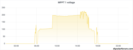
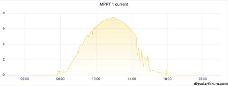
I don't suppose you have data logging to chart the string voltages, currents, and power output?

e.g. These charts show the behaviour of my small 2.22 kW 6S off-grid array yesterday (6 x Longi 375 W). Can see how long it takes for the voltage to get out of the hole it was in during the early part of the morning.

Screen Shot 2023-09-04 at 6.52.40 am.png
Screen Shot 2023-09-04 at 6.50.13 am.png

This is as much a statement on the (pretty ordinary) quality of the MPPT than the way the panels are shaded. Not all MPPTs are equal, some are much better than others. Mine is a cheap EASun 8 kW unit.

Behaviour in mid-afternoon is due to battery reaching full charge, and hence load being removed. Later in the afternoon, the encroaching shading results in a sharp voltage drop.
 
Ok, so i'm sold on the idea of optimizers.
Optimizer is 1/2 the cost of a panel. I you have that big a shading issue, you may be better off with splitting into smaller strings and buying extra MPPT's to feed your battery bus. Electric cars catch fire, not at a per-vehicle rate higher than non-electric cars but it makes good press. It is harder to put out. Solar panels have caught fire. Generally because of poor engineering choices, unlikely for most installations, but it makes good press. A little more concerning if it's on your roof, use common sense. The more modern the panel the less likely you will have issues.
 
I don't suppose you have data logging to chart the string voltages, currents, and power output?

e.g. These charts show the behaviour of my small 2.22 kW 6S off-grid array yesterday (6 x Longi 375 W). Can see how long it takes for the voltage to get out of the hole it was in during the early part of the morning.

View attachment 165861
View attachment 165860

This is as much a statement on the (pretty ordinary) quality of the MPPT than the way the panels are shaded. Not all MPPTs are equal, some are much better than others. Mine is a cheap EASun 8 kW unit.

Behaviour in mid-afternoon is due to battery reaching full charge, and hence load being removed. Later in the afternoon, the encroaching shading results in a sharp voltage drop.
The more expensive victrons are just as bad if not worse. MPPT algorithm is dead simple. My system only has a problem for about 20 minutes then it has full output so I don't mind it.
 
I just let the shading happen unless it was midday. I don't think it's worth it to buy optimizers if 99% of the day it is not shaded
 
Optimizer is 1/2 the cost of a panel. I you have that big a shading issue, you may be better off with splitting into smaller strings and buying extra MPPT's to feed your battery bus. Electric cars catch fire, not at a per-vehicle rate higher than non-electric cars but it makes good press. It is harder to put out. Solar panels have caught fire. Generally because of poor engineering choices, unlikely for most installations, but it makes good press. A little more concerning if it's on your roof, use common sense. The more modern the panel the less likely you will have issues.
Depends on the panel and optimizer but yes I agree. I don't see it being worth the money.
 
Back
Top