diy solar

diy solar

Service Meter Problems?

svetz

Works in theory! Practice? That's something else
Joined
Sep 20, 2019
Messages
7,298
Location
Key Largo
Another topic for your inner electrician....

UPDATE: It's bad data ... gigo .. the service meter is actually a CL-200... see the Crisis Averted post below...

The inspection for the new house for my mother-in-law listed an oddity. The service meter was 100 amps and just below that was a 100 amp disconnect. The oddity is that inside the house is a 150 amp load center. I thought the service was fairly small and toyed with the idea of having the meter changed out at some point to add on an elevator (she's 92).

Now that I've painstakingly traced all the wires from the circuit breakers I have learned the cursory inspection was all wet (in more ways than one, expecting an 1" of rain tomorrow after the 1" we had today and that storm is now called tropical depression 28). I found a second hidden load center in the downstairs area.

So, the guy we bought this off of was a retired fireman; I'm starting to think he liked fires.

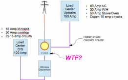
So, it turns out it really looks like this:
1603584471872.png

I verified the wire gauges were correct for the 150 and 100 amp load centers out to the meter, but the problem is the service entrance is only 100 amps. The house on average probably pulls under 15 amps. But if the stove is on and the hot water is on and both ACs are on while running the dishwasher and somebody turns on the vacuum... do I get glow in the dark wires from the pole?

Anyway, has anyone ever had to deal with something like this? I imagine I just call the power company and ask them to change the service. If I have to bring the exterior up to code it'll cost some big $. When I got my netmeter replacement they didn't make me do it. Guess it depends on what the gauge is from the pole to the meter as to how ornery they'll get.
 
Last edited:
Where is the service fuse in relation to all this? The CL100? So both load centres terminate on a common point / bus there with a 100A fuse between there and the outside world?

Looking at this out of curiosity from across the ocean where things are done differently.
 
Where is the service fuse in relation to all this?
The 100 Amp load center has it's breaker just below the service meter. The 150 amp load center has it's breaker built into the load center.

The CL100? So both load centres terminate on a common point / bus there with a 100A fuse between there and the outside world?
They both terminate on the backplane of the service meter.

You know, it has valid tags on the meter... so the power company must have been the ones that tapped it.
 
So there's no common service fuse between the premises and the grid, ie it's theoretically possible to draw > 100A if both the load centres are going hard? That'd be a problem ... ?

FWIW in my state, QLD, AFAIK for houses the service fuse is on the pole in the street, or equiv if underground. Mine is definitely on the pole. I think it's either 63A or 80A but could be 100A based on the wire run in my roof.

In other states I've heard it can be at the entry point on the building instead.
 
That'd be a problem ... ?
There might be an incidental fuse (i.e., the service meter back plane melts). You never know, @Supervstech might say it's done all the time.

Possibly I need to inspect the tags on the meter a bit closer and make sure there isn't any hot-glue holding things together.

Just realized it sounds like we're moving my mother-in-law into a slum.
Other than the mold, wiring, p traps, GFCIs, ventilation, roof, a few BFE items and about 50 other issues... it really it a nice place. Honest!

(And thanks everyone for your help on this and the other posts...want to get all this stuff fixed up before she does move down).
 
Wow. I sure hope there is a service fuse or equiv in there. ?
 
So you can draw 250A through a 100A meter.

Maybe put in a 200A fused disconnect, with service entrance hood (assuming overhead.)
Utility drops a suitable gauge wire to it and crimps to the wires you had dangling out of it, cuts off the old smaller wires.
Then you can connect the 150A and the 100A downstream of the 200A fuses.

I upgraded my sister's 30A screw-in fuse panel to 100A breaker panel years ago. I had a breaker routed over to the fuse panel, and the utility guy saw to just flip it and restore power. Wasn't expensive.
 
Yup, it is done all the time.
Home load calculations are WONKY! 12.5KW electric ovens count only as .25 of rated current, 85% total ampacity deductions, etc...
you have in excess of 250A load centers connected to the 100AMPS service drop, but rarely will the load exceed 100AMPS, so the utility just leaves the #10 free air service drop!!! Feeding your house.
You can request a 200A drop, but a new meter can and riser with weatherhead will need to be bought and installed by an electrician... and the electric company will require an inspection prior to reconnect.
 
So if I read @Hedges correctly it's up to the consumer to provide the fuse, the service from the electricity supplier is unprotected?
 
Last edited:
Well, normally a breaker right after the meter. If I draw over 200A, which would be too much for 2/0 in underground conduit from the utility, if would eventually trip. We're allowed to have our main breaker on a panel up to about 5' inside our house.

Utility has a fuse down the street, on the primary of a transformer (vault in my front yard) feeding half a dozen homes. When we had a power outage, they did something and replaced that fuse. At the transformer there also seemed to be shutoffs to disconnect individual drops.

If there was a short in the drop, unprotected by main breaker at the house, that would probably blow their fuse. In this case with six loads it seems sized reasonably well. That may not always be the case.

NEC 2008: Table 250.122 shows
200A, use 6 awg ground
1000A, use 2/0 ground

2/0 up to 3 wires in a bundle is rated 195A (homes have 2 current carrying conductors, so ampacity could have been a bit higher but NEC doesn't grant that)
So in the case of a dead short, 2/0 is supposed to be able to clear a 1000A fuse. If 6 homes at 200A each, transformer expected to supply 1200A, close enough that if primary similarly fused, should work. May have been sized assuming not all draw maximum.

"Supply side tap" for PV, PG&E allows 40A max, which limits overload of the drop in case you attach loads rather than PV inverters.

But for OP's case, 2.5x intended load is certainly excessive. 6.25 times the I^R heating of disconnect and wires.
 
Thanks! As always appreciate the information!
Yup, it is done all the time...calculations are WONKY! ...
My house isn't any different I guess. I have a 200 amp meter and two 150 amp breaker panels - so theoretically could draw 300 amps through it. Of course, with most stuff on (e.g., drier, microwave, lights, oven, d/w, ac) my clamp meter only read 80 amps.

I think I'll put my clamp meter around the upstairs inlet then turn everything on. Rinse and repeat for downstairs. See what she runs in total. I'll let you know.

...and the electric company will require an inspection prior to reconnect.
We get code changes from lessons learned every hurricane that passes through and that's a good thing. Things like the roof replacement will get brought up to code when it's fixed.
 
iStock-482671291.jpg
Turns out I'm an idiot.

The inspector may have written 100 amp service entrance, but he must have
been talking about the 100 amp circuit breaker right under the service meter.

The meter is a CL 200 and has appropriately sized wires coming into it.

The inspector couldn't see the "hidden" conduit, and probably just assumed the 100 amps was all there was.

Whew! I love it when I don't have to do anything!
So, no glow in the dark cabling for her!

Zeta
On the plus side, looks like Zeta (formerly known as tropical depression 26) will miss us. Good news for us, tree trimmers won't be there until Tuesday.
 
Last edited:
Well, normally a breaker right after the meter. If I draw over 200A, which would be too much for 2/0 in underground conduit from the utility, if would eventually trip. We're allowed to have our main breaker on a panel up to about 5' inside our house.

Utility has a fuse down the street, on the primary of a transformer (vault in my front yard) feeding half a dozen homes. When we had a power outage, they did something and replaced that fuse. At the transformer there also seemed to be shutoffs to disconnect individual drops.

Always interesting to see how things are done in other parts of the world.

In my area large-ish pole or pad mounted 3 phase transformer props up the surrounding area's low voltage grid. There are several transformers placed around that local low voltage grid so that no single transformer carries X houses directly they all contribute. There are several streets between each transformer. I'll pay attention next time I'm if I remember to give clearer picture and update this post. Each transformer has fuses on each input phase wire, 11kV 3 wire delta, and produces unfused 400V 4 wire wye/star. Each phase to a household is individually fused at the supply end, pole top or box on the ground for underground supply. Typical houses only have a single phase supply. It a premises needs to be disconnected the fuse can be pulled.

There isn't necessarily a master fuse inside the premises here, just a main switch which could also be a breaker. My supply comes in via aerial wire, to a small junction box under the eaves trough gutter, joins to my premises wire which runs in the roof space clean across the ceiling to the rear of the house and drops down to my externally mounted meter box where fuses, meters and switches are located. It's an older building with a grandfathered installation. The meter / main switch box these days has to be located on the front of or within a couple of meters of the front of the building if located on the sides now.

Compared to the gazillion breakers that tend to be seen in the USA my humble installation has ... 5 fuses. 8A lighting, 30A stove, 10A hot water, 2 x 15A GPO (ie wall outlets).
 
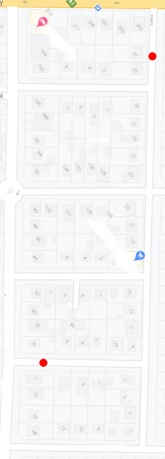
Last century thinking, pfft, going outside. No need any more, just use google maps. Red dots represent pole mounted transformers. Looking right at the next street across, not shown, there is a pole transformer in a similar position to the lower red dot in the picture. That should give an idea of the density of the transformers. The local low voltage block extends for some distance to the right. It's all fed off a common 11kV ring circuit with branches running down to the transformers. The block can be split up by opening pole top isolators for maintenance etc.

1603664033353.png
 
Back
Top