diy solar

diy solar

Setting aside wiring efficiency, what are the advantages/disadvantages of a higher voltage PV input with an MPPT charge controller

The thermal aspect of the cells is more important than this, IMO. At 0.3%/degree C, we can knock the panel Vmp down to being too close to battery voltage to be able to charge effectively, if at all. That's for a non-crappy panel, think 0.4% for a low quality one.
 
It looks like the power generated in the dawn and dusk hours is greater than neglible but less than substantial.
I think that is a perfect way to describe it, in fact I don't even remember the actual value, I just noted to myself that there is a difference, that series-connected arrays did harvest more energy all other things equal, but I suspect the reduction in resistive losses afforded by a higher PV voltage is materially more than these 'extra time harvesting' gains. A cherry on top of a nice chocolate gateau. Hmmm, hungry now...
 
The thermal aspect of the cells is more important than this, IMO. At 0.3%/degree C, we can knock the panel Vmp down to being too close to battery voltage to be able to charge effectively, if at all. That's for a non-crappy panel, think 0.4% for a low quality one.

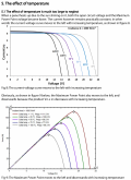
This section does a good job of illustrating the effect of temperature on voltage and on power

mppt-temp.png
 
One factor we probably haven't discussed fully enough is bypass diodes in series and parallel configurations. I'm still trying to fully wrap my head around the specific implications of Cal's point about bypass diodes having a negative effect on some PV arrays wired in parallel.

I have done a substantial amount of research into partial shade performance over the past few months and never came across this information until he brought it up, since then I've been able to find mentions of it here and there, but so far I haven't been able to find a single PV manufacturer, MPPT manufacturer, or article on partial shade mitigation that acknowledges the problem, which is crazy to me. I suppose there just really isn't much attention paid to off-grid, parallel wiring, or optimizing for partial shade since the vast majority of the industry is focused on grid connected, stationary, non-shaded, high voltage arrays.

To reiterate his point, a bypass diode allows current to flow around a shaded cell or group of cells, but in doing so it decreases the voltage of the panel as a result of taking a group of cells out of the series (usually 18 cells for 12v panels, 20 for 60 cell panels, or 24 for 72 cell panels). In doing so, if the panels are wired in parallel, voltage may drop to a point where it falls below the battery voltage. The higher the PV array voltage is relative to the battery voltage, the less likely this is to happen. As Cal pointed out, the most vulnerable are matched panels '12v' panels, with 12v batteries.

But even small series connected arrays or 60 or 72 cell panels paired to 12v battery banks could face problems if two of the three strings were shaded. This is causing me to rethink a lot of what I knew about partial shade performance.

One question that I would like to know the answer to is what happens if all three strings of cells in a panel are shaded, in a series connected pv array. does one of the bypass diodes, bypass the whole panel, or will the whole string be brought down by the shaded panel?
 
Has anyone heard of FOZHS? Stands for forward only zero hot-spot. I think this is also to do with partial shading conditions where the shaded cells would be fed current. Worth a Google.
 
One question that I would like to know the answer to is what happens if all three strings of cells in a panel are shaded, in a series connected pv array. does one of the bypass diodes, bypass the whole panel, or will the whole string be brought down by the shaded panel?

Really comes down to how those diodes are arranged. I've not cracked open the connector box on a lot of panels, but I have opened a few. I've seen panels with bypass diodes for half the panel and an over all diode that bypasses the whole panel. That'd probably be done for power loss, only take a single 0.6v hit across one diode instead of 1.2v for two.
 
  • Like
Reactions: Dzl
View attachment 13996

Now don't get me wrong, not a lot of current is happening at these low solar irridiance times, so even though the voltage very quickly rises, current is still low, so low power but, anything times zero is zero, and the parallel-connected SCC is just not on during these very early and late periods. And as a very famous shopping chain in the UK says, "Every little helps".

Edit: Corrected typo. Can't correct the one in the picture, though!

I sure would like to see measured test results. How many amp-hrs do you estimate are under the shaded area of your plot? Compare those gained AH to the ones lost over the entire day by operating at a higher voltage level. That difference may be 2%.

Once a PV cell starts conducting current then voltage should pop up as well. It's very hard to believe there's an hour difference. My mppt charge controller reverts to pwm when the voltage differential isn't large enough to operate the buck regulator within the charge controller. Perhaps your charge controller doesn't have that feature?
 
My mppt charge controller reverts to pwm when the voltage differential isn't large enough to operate the buck regulator within the charge controller. Perhaps your charge controller doesn't have that feature?

So in this case (when irradiance is too low for the MPPT to operate at the MPP and it falls back to PWM) how would this look in practice? Am I correct in understanding that there has to be a positive voltage differential between the array and the battery bank for any current to flow. So the controller would act as a PWM controller in the voltage band >Vbat < MPPT startup voltage?

On an unrelated note, can you provide any input on this question:
One question that I would like to know the answer to is what happens if all the strings of cells in a panel are shaded and every bypass diode is activated, in a series connected pv array. does one of the bypass diodes bypass the whole panel, or will the whole string be brought down by the shaded panel?
 
Last edited:
Some controller do support effectively putting the array across the battery in low power situations. Once power rises enough from the panels they go into MPPT mode. TBH I think that is more of a gimmick than a feature, the power gained by doing that is pretty low even in abnormal weather. The MakeSkyBlue controllers supposedly do it, but in my experience it's more of a pot luck thing with them. If they do actually do it they usually get stuck there indefinitely, ie never change to MPPT mode, or never do it instead hiccoughing repeatedly in and out of MPPT mode until there is enough power from the panels to stay in MPPT mode

(waits for MakeSkyBlue crowd to step in and say I'm a liar)
 
So in this case (when irradiance is too low for the MPPT to operate at the MPP and it falls back to PWN) how would this look in practice? Am I correct in understanding that there has to be a positive voltage differential between the array and the battery bank for any current to flow. So the controller would act as a PWN controller in the voltage band >Vbat < MPPT startup voltage?

On an unrelated note, can you provide any input on this question:
One question that I would like to know the answer to is what happens if all the strings of cells in a panel are shaded and every bypass diode is activated, in a series connected pv array. does one of the bypass diodes bypass the whole panel, or will the whole string be brought down by the shaded panel?

A mppt controller needs minimum 2 to 3V headroom between Vbat and Vmp. If my controller does not have this headroom it will make a direct connection (mosfet) between battery and panel. Though it's called pwm operation, here is no on/off switching until the setpoint voltage is met. During panel low voltage operation pwm mode is more efficient than mppt. In general, mppt is only 5 to 8% more efficient than pwm.

In the scenario where we got 2 panels in series and one panel is fully shaded (generating 3A) and the un-shaded panel outputs 6A then the 6A will go through the bypass diodes of the shaded panel. That could be 2 diode drops. You could also connect a bypass diode across the shaded panel inputs and then the 6A will only go through just one diode.

I believe if the panels were in parallel then the fully shaded panel will help make this setup more efficient. Total current will not be 6 + 3 = 9A, but perhaps 7A output as Vmp will not be equal.
 
I sure would like to see measured test results. How many amp-hrs do you estimate are under the shaded area of your plot? Compare those gained AH to the ones lost over the entire day by operating at a higher voltage level. That difference may be 2%.
A challenging ask as I did these tests at least a couple of years ago and since I've had my panels connected based on my tests to harvest maximum energy i.e. connected in series. I only had two panels in the test, both 100W. So in theory I would be able to harvest around 400Wh, 2% of that is 8Wh. So the question is was the total Wh generated in the series configuration more than 8Wh above the total generated in parallel? My gut instinct is telling me it was in tens of Wh's, but that unfortunately is well within the vagaries of solar output over the days I was doing the test.

An inconclusive answer but, if you lift up out of the detail for a moment and assume that this 'higher Voc / Vbat differential = higher inefficiency' is real, then I can also assume my MPPT also incurred these losses during my tests, and yet I can say with confidence that the series-connected array always won out over the parallel-connected array, every time in every test. I remember this quite distinctly.
One question that I would like to know the answer to is what happens if all three strings of cells in a panel are shaded, in a series connected pv array. does one of the bypass diodes, bypass the whole panel, or will the whole string be brought down by the shaded panel?
Bypass diodes do not block the flow of current from shaded strings, they just avoid the scenario where the entire array's current flows through the shaded string causing power to be dissipated within the shaded cells and 'hot spots' to form. The current that is generated (I mean, unless the entire string is shaded i.e. zero current) still flows from the shaded string with the remaining current flowing through the bypass diode. So what happens? You just get less current, therefore less power from the panel. I would expect some impact on Voc but probably not a lot.

This lowered panel power effects the MPP of the array, so the MPPT controller will re-baseline by altering the effective resistance of the load as presented to the array, therefore once again running at the maximum power point. and the cycles starts again, hundreds of times a second.

The more shading occurs, the less current is generated, the more bypass diodes have to work, the more they themselves dissipate power, the less overall power you get.

I would expect this to be overall quite a linear relationship i.e. % shading is approximately directly proportional to power output, but I have never tested this.
That'd probably be done for power loss, only take a single 0.6v hit across one diode instead of 1.2v for two.
You'll find that most, if not all, PV panels use Schottkey diodes, which only have 0.2 - 0.3V drop across them in operation.
 
p.s. This is also why series-connected strings are impacted more by partial shading than parallel connected strings: in a series string, the lowest current dictates the string current, in a parallel string, the lowest voltage dictates the string voltage but string voltage is not so much affected by partial shading, I mean, you still get a reduction in power but it doesn't collapse in the same way series-connected strings do.

This is why I always recommend series connecting your array as far as possible (i.e. your SCC allows), unless partial shading is an issue, whereby you can optimise the array by introducing parallel strings. Partial shading could be as simple as a tree causing shadows within the sun's path across the sky, or even the likelihood of bird poop covering cells.
 
The number of parallel sets (single panels or strings of) comes into play when using MPPT. My main array is 10 190W panels arranged 5 parallel sets of 2 in series in order to live within the voltage requirements of the controller. As the day progresses shadows fall across the sets at this time of year. If only one set is shaded, reducing its voltage, the MPPT controller (Victron) tends to stay at the higher voltage of the rest of the array since pulling the entire array down to where the partially shaded set can contribute results in lower power out of the array. This effectively cuts off the lower voltage set but the overall result is better. As the shading moves so that more sets are shaded the Victron eventually sees a higher power point at a lower voltage so it pulls the entire array down to there.
 
Last edited:
Bypass diodes do not block the flow of current from shaded strings, they just avoid the scenario where the entire array's current flows through the shaded string causing power to be dissipated within the shaded cells and 'hot spots' to form.

Interesting I hadn't considered this, I had been imagining the bypass diodes effect similar to a toggle switch, "either current flows through the solar cell string OR through the bypass diode" I hadn't considered that it could be an "and" situation where current has two parallel paths when the diode is activated and some could flow through both.

The current that is generated (I mean, unless the entire string is shaded i.e. zero current) still flows from the shaded string with the remaining current flowing through the bypass diode.

As I understand it (full disclosure, I don't :)), you only need one fully shaded cell, for current to drop to zero. Because cells are all connected in series, a cell that won't allow any current to pass through would constrict the current of the entire series, until the bypass diode is activated and lets current from the unaffected strings flow around the shaded string. But then I would imagine the string of the cells in the string with the shaded cell would not pass any current. Am I misunderstanding something?

So what happens? You just get less current, therefore less power from the panel. I would expect some impact on Voc but probably not a lot.

So in your understanding, Voltage isn't dramatically reduced, because a partially shaded string of cells isn't totally taken out of the circuit (current is just given another path to flow around it), so keeps contributing voltage and whatever current it can? This seems to be at odds with @Cal's understanding, I wonder if we can reconcile this.
 
Last edited:
Bypass diodes do not block the flow of current from shaded strings, they just avoid the scenario where the entire array's current flows through the shaded string causing power to be dissipated within the shaded cells and 'hot spots' to form. The current that is generated (I mean, unless the entire string is shaded i.e. zero current) still flows from the shaded string with the remaining current flowing through the bypass diode. So what happens? You just get less current, therefore less power from the panel. I would expect some impact on Voc but probably not a lot.

I'm not quite sure what you are saying. If the bypass diode is conducting then the PV cells associated with this diode will produce zero current.
 
Because I'm a visual learner, I drew this out to help myself conceptualize it, and to give us some visual anchor points for the discussion:

Untitled Diagram-1.png
With a single fully shaded cell (for example a leaf covering the cell), I'm pretty sure the bypass diode would be activated, and based on Cal's understanding the entire string of 20 cells would be bypassed and Vmp would drop by 33%. This is the usual test done in most videos, covering a cell or multiple cells with a piece of cardboard or something.

However in practice, I think the third (righthand) example would be most common. partial (as in shaded, but non-zero irradiance) would be more common. A tree branch or semi-diffuse shadow causing some shade. In this situation at what point would the bypass diode activate, or would it not activate at all until current being conducted by the string falls to near zero?
 
I'm not quite sure what you are saying. If the bypass diode is conducting then the PV cells associated with this diode will produce zero current.
No, I don't believe this is the case. I'm going back a bit now to when I studied this but I don't think current just stops because the bypass diode is active. PV cells are essentially constant current source in series with, as they don't superconduct, a resistance that generates a potential difference across it. As irradiance falls, due to partial shading, a lower current is generated, which reduces the potential difference and forward biases the bypass diode which begins to bypass current from the remaining cells. But if memory serves, that reduced current still flows from the partially shaded string. As mentioned above, the bypass diode doesn't prevent the, albeit reduced, current from the partially shaded string flowing out of the panel but does prevent the higher higher current from the fully irradiated cells flowing through it.

I do accept the possibility that I'm wrong on this, it's been a while since I've thought about it in this much depth, but that's my understanding.
and based on Cal's understanding the entire string of 20 cells would be bypassed and Vmp would drop by 33%.
I don't believe this is the case. I guess it could easily be tested. Yes, the overall power output will drop but I don't think the overall Voc will change much. PV cells can be thought of as constant current sources that vary their output current depending on solar irradiance. Most IV curves I've seen have a pretty stable voltage at all but the lowest levels of irradiance.
 
  • Like
Reactions: Dzl
The panel containing the partially shaded string will become unloaded as the other paralleled panels have a higher voltage/current maximum under load. That then allows the shaded panel to float up to that higher voltage, the shaded cell still has light falling on it, just less so it can still produce current just not much of it. The overall effect is that the shaded panel contributes very little in a parallel situation, dictated by the current that can actually flow through the shaded cell. Overall array current falls if the load is capable of passing full current of the array, but voltage is maintained. If the load is sufficient to pull the entire array down to the new Vmp of the shaded panel, it will pass full current again.

In series the shaded string again contributes little for the same reason but now the current from the other panels and non-shaded string is still allowed to flow past the shaded string using the bypass diode. Array voltage falls, but array current remains the same, putting the nature of the bypass diode itself aside temporarily, assuming the load can adjust to the lower voltage of course and that the load can pull sufficient current from the array to make the effects of lower current through the shaded cell apparent. If the load can't do that array voltage will remain at the high point.

Q: Why does current flow? Answering that will make understanding all this a bit easier.
 
Last edited:
  • Like
Reactions: Dzl
No, I don't believe this is the case. I'm going back a bit now to when I studied this but I don't think current just stops because the bypass diode is active. PV cells are essentially constant current source in series with, as they don't superconduct, a resistance that generates a potential difference across it. As irradiance falls, due to partial shading, a lower current is generated, which reduces the potential difference and forward biases the bypass diode which begins to bypass current from the remaining cells. But if memory serves, that reduced current still flows from the partially shaded string. As mentioned above, the bypass diode doesn't prevent the, albeit reduced, current from the partially shaded string flowing out of the panel but does prevent the higher higher current from the fully irradiated cells flowing through it.

Let me see if I am correctly interpreting your understanding. I believe what you are saying is that in a partial shading scenario (no cell is experiencing zero irradiance, but some cells in a string are experiencing substantially reduced irradiance), the bypass diode would activate, and current from the two non-shaded cells strings would flow through the bypass diode, but the shaded string would still produce some current, and because voltage is relatively stable until <200W/m^2, so long as the shaded cells were above that level, the operating voltage of the panel would be pretty close to what it would be if unshaded?

I don't believe this is the case. I guess it could easily be tested. Yes, the overall power output will drop but I don't think the overall Voc will change much. PV cells can be thought of as constant current sources that vary their output current depending on solar irradiance. Most IV curves I've seen have a pretty stable voltage at all but the lowest levels of irradiance.

Forgive the non-technical terms below:
By introducing an alternate parallel path (the bypass diode) for current to flow, wouldn't this essentially lower the 'electrical pressure (voltage)' of the circuit, and most all the current would now flow through the bypass diode (which has a difference in voltage of <1V across it) as opposed to through the string of shaded PV cells (which have a difference of 10V across them in the case of a 60 cell panel)?

I'm quite aware that I'm wandering waaaay out beyond my level of understanding right now, so its quite likely I'm fundamentally misunderstanding at least one or two things.
 
Last edited:
the bypass diode would activate, and current from the two non-shaded cells would flow through the bypass diode,
No, I don't believe this to be the case, if memory serves, the bypass diode is for the other cells within the panel (or other panels within the string if connected in series). I've got it in my head the the partially shading string just provides a lower current in the same way as it did before i.e. NOT through the bypass diode. I'm going to have to refresh my knowledge on this ... it's been a while and I've slept since learning it!!
because voltage is relatively stable until <200W/m^2, so long as the shaded cells were above that level, the operating voltage of the panel would be pretty close to what it would be if unshaded?
Yes, that sounds about right.
By introducing an alternate parallel path (the bypass diode) for current to flow.....
I always struggled with the voltages across PV cells and bypass diodes and, to a lessor degree, blocking diodes because the PV cell itself can be be modelled as PN junction i.e. a constant current source in parallel with a diode, so you have 0.6V across the cell, then when the bypass diode conducts your have 0.2-0.3V across that, and 0.2-0.3V across the blocking diode!!! I never really nailed my understanding of that.
wouldn't this essentially lower the 'electrical pressure (voltage)' of the circuit,
Each PV cell generates a current which effectively forward biases itself (!) generating a 0.6V potential difference across it, add all these 0.6V up and you end up with the panel's Voc e.g. 0.6V x 36 cells = 21.6V. If one cell is partially shaded, generated current is reduced but if current is still flowing, the cell's PN junction will still have 0.6V across it, therefore overall voltage will not be impacted too much (I'm convinced there is some impact because a PV cell/panel has an internal resistance that will create a change in potential difference as current changes).

If panel Isc is, for example, 6.5A for a 100W 36-cell panel, then each cell is generating 180mA. If one cell is partially shaded so that it only generates, say, 80mA then without bypass diodes the entire panel's output would drop to 80mA (at 21.6V). With bypass diodes, only the series string with the partially shaded cell would be reduced to 80mA (at 12 cells x 0.6V = 7.2V), so you'd have:
  1. Series string 1 (Isc / Voc): 2.16A / 7.2V
  2. Series string 2 (Isc / Voc): 2.16A / 7.2V
  3. Series string 3 (Isc / Voc): 80mA / approx 7.2V
I think! o_O

Remember, though, that a panel doesn't output Isc nor Voc in normal operation, it outputs Imp at Vmp with a MPPT SCC. The numbers above are just to illustrate the point.
 
Back
Top